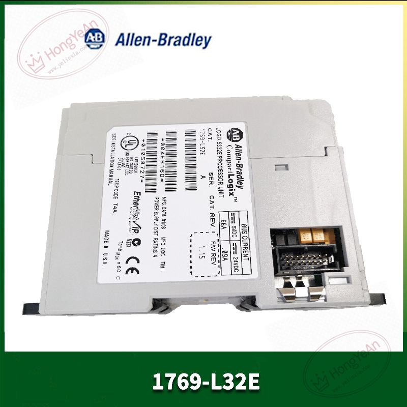
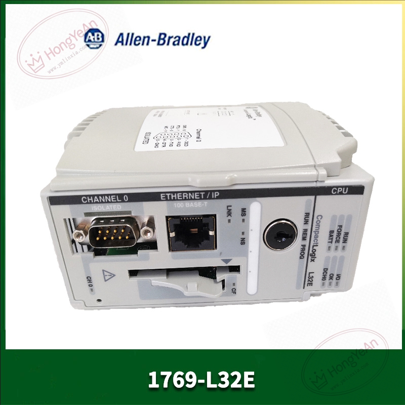
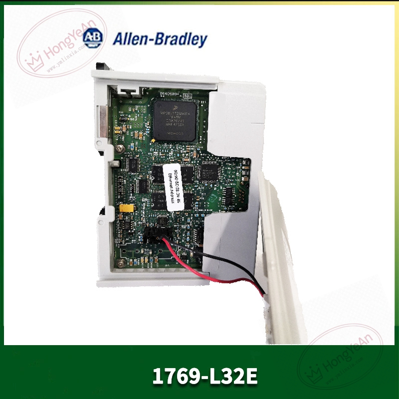
Description
Key Technical Parameters
Slot requirement: Single‑slot installation, belongs to 1769 CompactLogix series rack User memory: 750KB program and tag data memory; supports CompactFlash card for project backup Communication interface: 10/100Mbps EtherNet/IP RJ45 port; Channel0 RS‑232 serial port Protocol support: EtherNet/IP, CIP, Modbus‑TCP, DF1, DH‑485 Max local I/O modules: Up to 16 pieces of 1769‑series I/O modules Backplane load: 650mA @5VDC Programming software: Studio 5000 / RSLogix5000 V16 and above Status indicator: RUN, FAULT, FORCE, OK, Ethernet link LED indicator Operating environment: 0‑60℃ cabinet‑mount installation, non‑condensing; UL, CE certification Note: No onboard I/O; all field signals rely on external 1769 I/O modules
Practical Application Features
Tag‑based programming mode, convenient for recipe storage, data logging and complex logic processing. Native EtherNet/IP interface can communicate with HMI, remote I/O and other Rockwell controllers, no extra gateway required. RS‑232 serial port connects serial devices such as barcode readers and old‑type instruments. Supports online force function, convenient for field equipment debugging. Rich internal diagnostic tags can upload fault information to HMI for operator viewing. Suitable for assembly machinery, packaging equipment, water‑treatment small‑scale control projects.
Field Installation & Commissioning Guidance
Power‑off the rack before plugging CPU module, lock front latch securely. Add 1769‑L32E into Studio 5000 hardware configuration, match firmware version with physical hardware. Assign IP address by BOOTP‑DHCP tool; default fallback IP 192.168.1.1 without BOOTP server. Complete hardware configuration for each 1769 I/O module, verify total quantity does not exceed 16 modules limit. Set serial‑port protocol parameters according to connected serial peripherals. Download project program, clear fault status and switch controller to RUN mode. Adopt shielded network cable for industrial environment; separate communication wiring from high‑power frequency‑converter cables. Keep good cabinet grounding to reduce electromagnetic interference risk.
In‑Site Troubleshooting Reference
- Red FAULT LED constant on: Firmware‑version mismatch, program corruption or hardware damage; re‑download valid program.
- Cannot switch to RUN mode: Uncleared major fault bit, I/O configuration mismatch, eliminate fault first.
- EtherNet/IP communication failure: Wrong IP subnet, network cable damage, switch‑port failure; use BOOTP tool to reset IP.
- Intermittent remote I/O timeout: Improper RPI setting, excessive CIP connection resources, on‑site power‑grid interference.
- RS‑232 no communication: Serial‑cable fault, protocol‑parameter mismatch, terminal loose contact.
- Controller cannot identify expansion I/O: Exceed maximum 16‑module limit, poor backplane contact, inconsistent hardware configuration.
-300x300.jpg)


Reviews
There are no reviews yet.