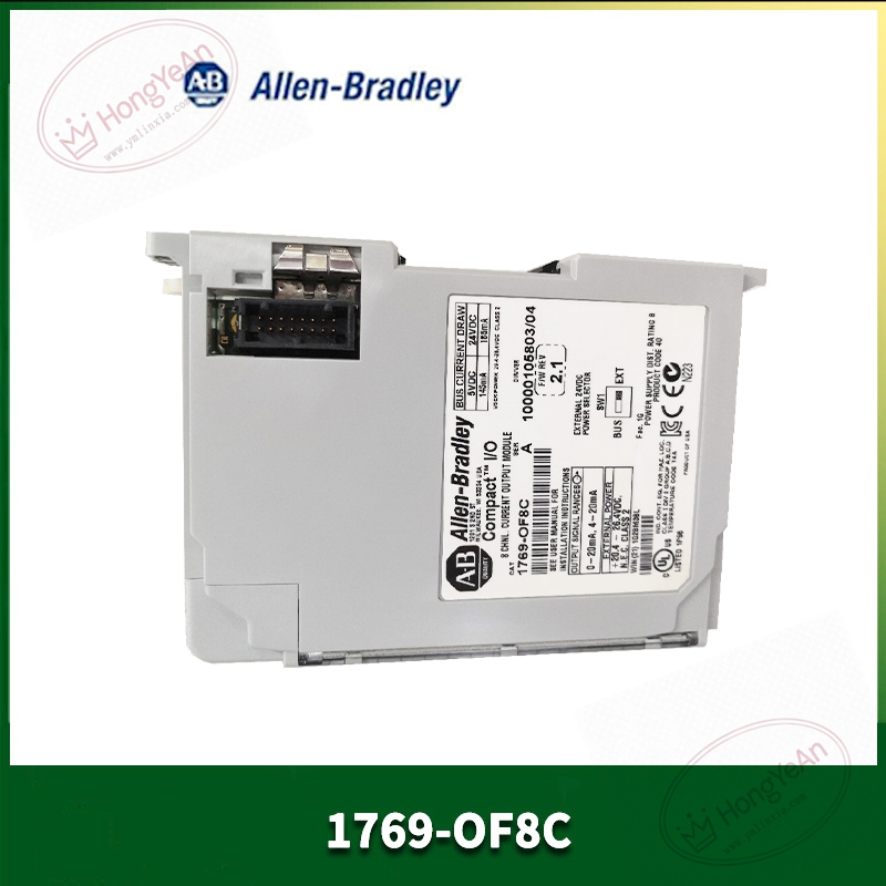
Description
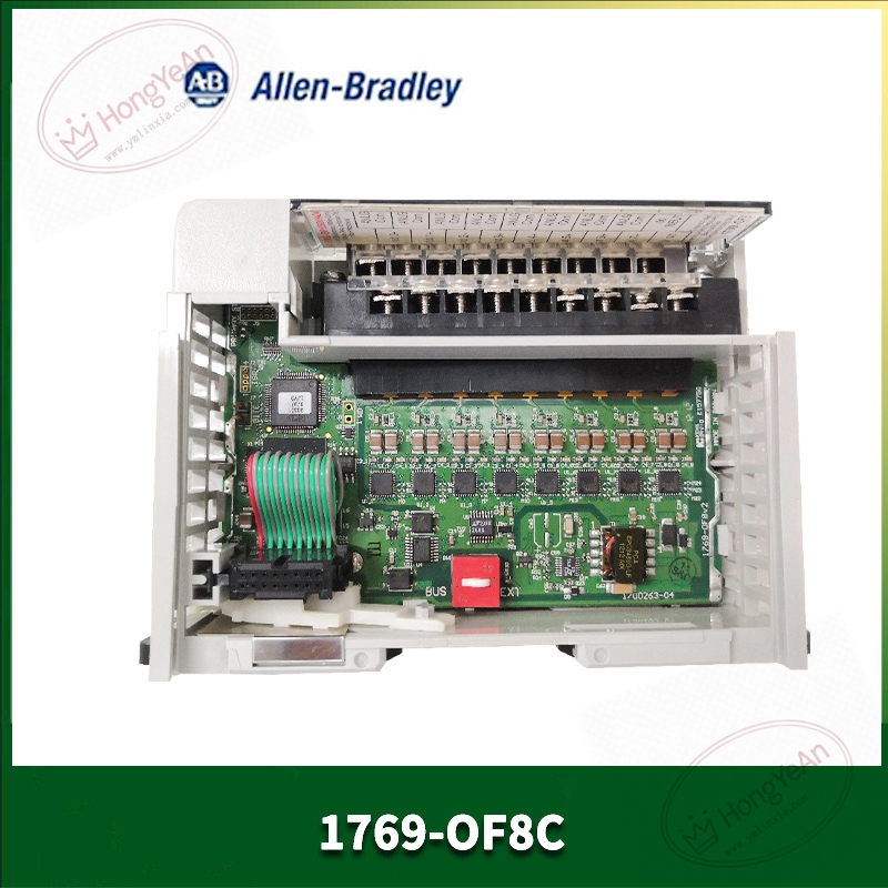
Key Technical Parameters
Slot requirement: Single‑slot installation, fits any vacant slot on 1769 CompactLogix local or expansion rack Channel specification: 8 single‑ended current output channels; each channel software‑selectable 0‑20 mA or 4‑20 mA range Resolution: 16‑bit DAC resolution Measuring accuracy: ±0.1 % full‑scale at 25℃ Update speed: Typical 5 ms for full 8‑channel update Isolation: 500V AC isolation between field‑side and backplane circuit Backplane load: 145 mA @5VDC; 160 mA @24VDC external field power consumption Diagnostic function: Per‑channel open‑circuit detection, fault status uploaded as controller tags Hot‑swap: Supported under non‑hazardous‑location condition Status indicator: Module OK status LED Programming tool: Studio 5000 / RSLogix 5000 Operating environment: 0‑60℃ cabinet‑mount installation, non‑condensing; UL, CE certification Note: Only current output, no voltage output function
Practical Application Features
Each channel independently configures signal range, flexible for multi‑loop process control projects. Open‑circuit diagnosis can quickly report broken field wiring to PLC, convenient for HMI fault alarm display. Supports fault‑mode setting: hold last value / user‑defined output value when communication fails. Hot‑swap function allows module replacement without powering off whole rack during equipment maintenance. High‑density 8‑channel design reduces chassis slot occupation for multi‑analog‑point projects. Widely applied in water treatment, chemical auxiliary control, heating furnaces and packaging‑machine closed‑loop adjustment.
Field Installation & Commissioning Guidance
Insert module into any vacant slot of 1769 rack and lock front latch firmly. Hot‑swap operation is only permitted in non‑explosive‑risk area. Provide isolated 24VDC field power supply for analog output loop; pay attention to wiring polarity. Add 1769‑OF8C into Studio 5000 hardware configuration, set signal range, fault mode and channel enable parameters channel‑by‑channel. Adopt shielded twisted‑pair cable for analog field wiring; separate analog wiring from inverter and high‑power motor cables to suppress interference. Complete signal scaling configuration inside PLC tag, match 4‑20mA physical signal with engineering value. After downloading configuration, perform point‑to‑point test with multimeter to verify output current accuracy.
In‑Site Troubleshooting Reference
- Module OK indicator off: Check chassis backplane power supply, module seating condition or hardware damage.
- Output current zero: Channel not enabled in configuration, fault‑mode set to zero output, field power supply missing.
- Open‑circuit fault alarm triggered: Field cable broken, field device terminal loose contact, loop load open‑circuit.
- Output value deviation obvious: Improper scaling parameter, excessive on‑site electromagnetic interference, verify loop load resistance complies with module specification.
- Output stuck at fixed current value: Improper clamp‑limit setting inside module properties, re‑configure upper/lower limit parameters.
- Intermittent output jitter: Poor cabinet grounding, analog cable shielding failure, optimize field‑site grounding treatment.


-300x300.jpg)
Reviews
There are no reviews yet.