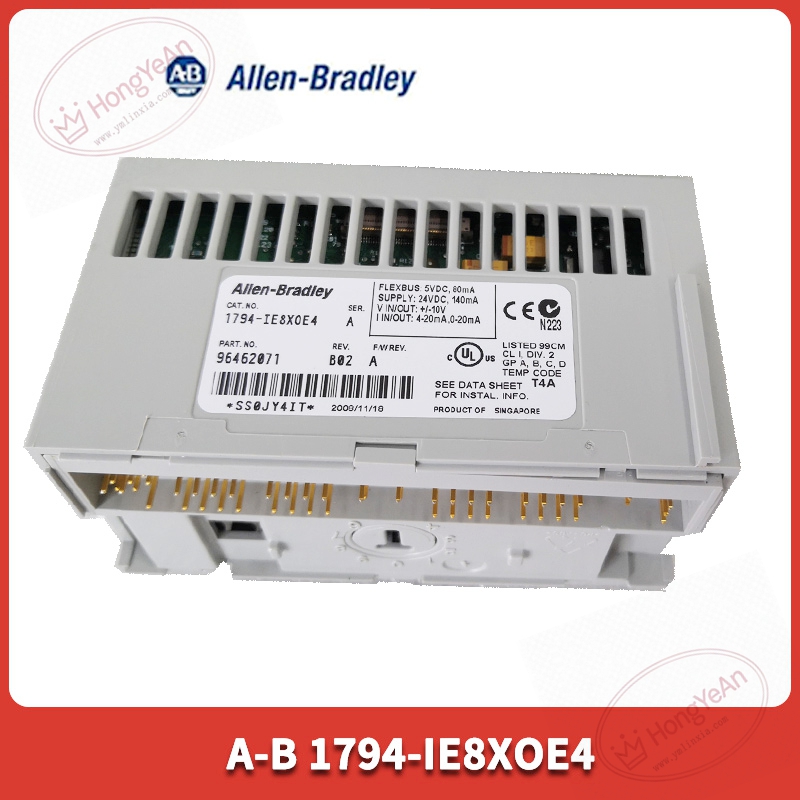
Description
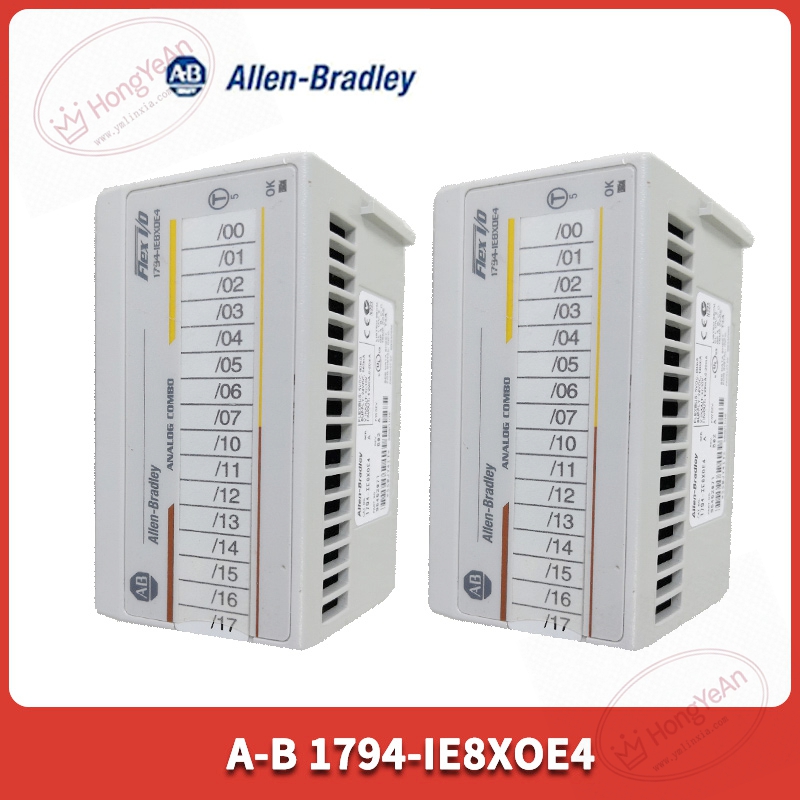
Key Technical Parameters
Installation mode: Install onto dedicated 1794‑TB2 / TB3 terminal base; module and terminal base are sold separately Channel configuration: 8‑point single‑ended analog input; 4‑point single‑ended analog output Signal range: 0‑20mA, 4‑20mA (software configurable per channel) Resolution: 12‑bit conversion resolution Accuracy: ±0.2% full‑scale under 25℃ ambient temperature Conversion speed: All‑input channels 256μs update rate; output response time approx 1.024ms Power requirement: 24VDC field power supply; module draws power from Flex bus via terminal base Communication: Flex I/O backplane bus, connect to 1794‑ADN remote I/O adapter, communicate with ControlLogix / SLC500 PLC Status indicator: Module OK LED status lamp Supported software: RSLogix5000 / RSLogix500 Operating environment: Operating temperature 0‑60℃, storage‑40‑85℃; cabinet‑mount installation, UL, CE certification Note: Non‑isolated between channels; analog signal wiring requires shielded twisted‑pair cable
Practical Application Features
Integrates analog input and output within one module, saves terminal base and cabinet slot resources. Input channels collect pressure, flow, level transmitter 4‑20mA signals; output channels drive regulating valves and frequency‑converter analog set‑point. Supports channel‑by‑channel signal range selection to adapt different field instruments. Supports fault‑output mode setting, hold last value or preset fixed value when communication breaks. Distributed Flex I/O architecture places module close to field sensors and actuators, shortens analog cable length and reduces signal interference risk. Mainly applied in water‑treatment, chemical auxiliary control, material‑handling and old‑production‑line maintenance‑replacement scenarios.
Field Installation & Commissioning Guidance
Power off terminal‑base power before installation; set key switch on terminal base to position 5 for this module. Ensure Flexbus connector fully pushed‑out, align module with terminal‑base guide groove and press firmly until latch locks. Use CAT5e shielded twisted‑pair cable for analog signal wiring; separate analog cables from inverter and high‑power motor cables. Complete hardware configuration in programming software, set signal range, fault output mode for each channel. Match remote‑I/O adapter node address when deploying distributed Flex‑I/O racks. After downloading configuration, use multimeter to test input collecting value and output current signal channel‑by‑channel. Check cabinet grounding quality to restrain analog signal drift caused by site electromagnetic interference.
In‑Site Troubleshooting Reference
- Module OK LED off: Terminal‑base power failure, poor module seating, damaged Flex bus connector.
- Analog input reading zero or frozen: Field transmitter power missing, signal‑loop wiring break, wrong channel range parameter setting.
- Output channel no current output: Channel not enabled in configuration, field loop open‑circuit fault.
- Obvious signal fluctuation: Poor shielding‑ground, analog wiring mixed with high‑power cables; add signal filter parameter inside module properties.
- Intermittent communication failure: Bad remote‑I/O communication cable, wrong node‑address dial‑switch, broadcast storm on control network.
- Channel value deviation large: Re‑calibrate scaling parameters; check field transmitter nameplate and loop load resistance.

Reviews
There are no reviews yet.