Description
Key Technical Parameters
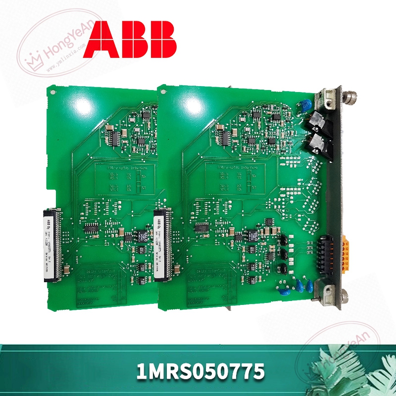
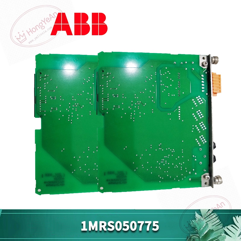
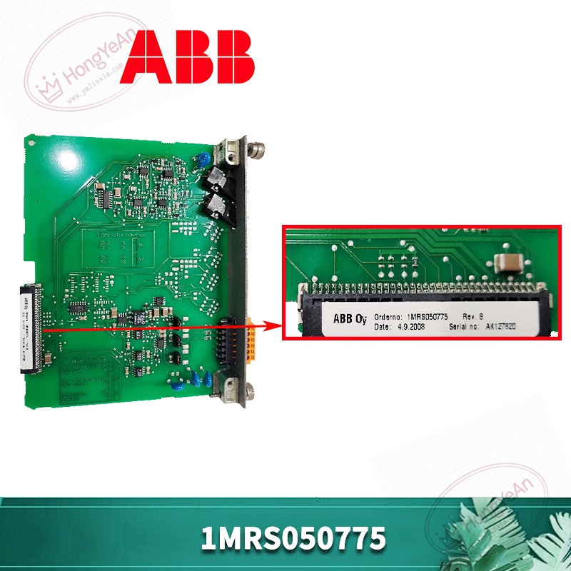
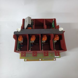
Device Type: Plug‑in circuit board assembly for protection relay hardware Part No: 1MRS050775 Mechanical form: Standard rack‑insert PCB board with metal locking structure Working power: Supplied through the host relay internal power circuit On‑board circuit: Signal conditioning circuit, data transmission circuit and peripheral auxiliary circuit Status feedback: Realized through host device indicator lights, no independent display on the board itself Operating ambient temperature: ‑25℃ ~ +70℃, non‑condensing inside cabinet Storage temperature:‑40℃ ~ +85℃ Humidity requirement: 5%‑95% relative humidity, non‑condensing environment Compatibility: Matches specific ABB protection relay hardware; cannot be used for other series controllers Certification: Meets industrial CE and UL standards for power‑industry equipment Important Note: This board cannot run independently. It must be installed inside matched relay hardware. Hot‑swap under live conditions is forbidden. Component version needs to keep consistent with original device configuration.
Practical Application Features
Processes collected electrical signals and completes internal data forwarding for the protection relay main unit. Cooperates with main control logic of protection equipment to assist in realizing over‑current, over‑voltage and other protection‑related functions. Compact plug‑in structure supports convenient disassembly‑assembly for on‑site maintenance work. Industrial‑grade PCB and component layout adapt to electromagnetic interference environment inside power‑distribution cabinets. Can restore partial equipment functions when original circuit board gets damaged during site faults. Common usage scenarios: substation protection cabinets, power‑plant auxiliary protection equipment, industrial high‑voltage cabinet protection units, spare‑part replacement for aging protection‑relay installations.
Field Installation & Commissioning Guidance
Cut off all AC and DC power supply of the whole protection relay before replacement. Follow power‑industry safety operation specifications strictly. Take out the old circuit board carefully, insert 1MRS050775 into the correct slot and lock the metal fastener tightly to guarantee stable back‑plane contact. Check that there is no foreign matter or dust inside the slot. Visually inspect the new board for scratches, burnt components and abnormal solder joints. After installation, restore relevant internal wiring inside the relay cabinet. Double‑check every connection point. Power on the protection relay step‑by‑step, observe host device indicator status, confirm no hardware fault alarm pops up. Carry out function verification: check measurement value reading, protection signal feedback and communication status of the whole relay unit. Ensure cabinet ventilation stays in good condition. Avoid long‑time running under excessive cabinet inner temperature. For long‑term operating equipment, perform regular inspection for aging risks of electrolytic components on circuit boards.
In‑Site Troubleshooting Reference
- Host relay reports hardware fault after board replacement: Poor back‑plane slot contact; foreign residues inside slot; mismatched hardware revision between new board and host unit. Re‑insert or check version compatibility.
- Measurement data reading abnormal: Internal signal circuit damage on the board; bad contact of slot pins. Clean slot contacts or re‑check board status.
- Intermittent alarm without fixed rules: Cabinet internal overtemperature; severe electromagnetic interference; loose locking fastener causing unstable contact. Improve heat dissipation and re‑tighten module.
- Protection function response abnormal: Distinguish whether problem comes from this auxiliary circuit board or main CPU unit of relay; separate inspection is required.
- Communication failure of whole relay: Check whether this board takes part in data transmission path; inspect board circuit damage and back‑plane connection status.
- Board damaged after site short‑circuit accident: Voltage surge invades inner circuit. Replace the board, meanwhile inspect other internal components of the protection relay for secondary damage.
-300x300.jpg)
Reviews
There are no reviews yet.