Description
Key Technical Parameters
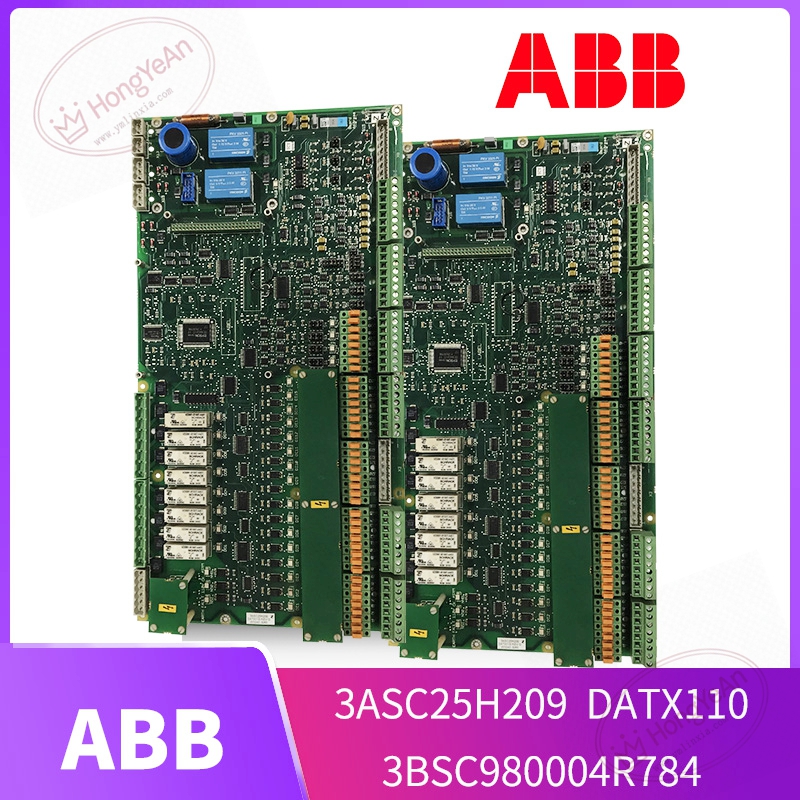
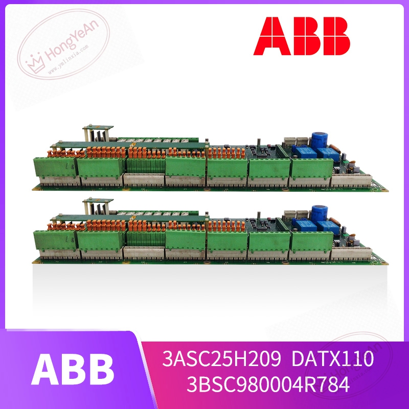
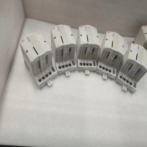
Device Type: Rack‑mount I/O interface printed circuit assembly Reference Codes: 3ASC25H209, functional designation DATX110, hardware code 3BSC980004R784 Signal Channels: Multiple digital input paths and built‑in relay output channels for field device interaction On‑board Components: Terminal connector blocks, signal conditioning circuits, relay units and local status indicator LEDs Operating Supply: Powered by internal low‑voltage power from the host drive or control rack Mechanical Structure: Standard rack‑installation PCB assembly; spring‑loaded screw terminals for field cable termination Operating Ambient: 0℃ ~ +60℃, non‑condensing indoor cabinet environment Storage Condition:‑25℃ ~ +70℃ for spare‑part preservation Compatible Hardware: Matched with certain ABB medium‑power drive systems and older‑generation power‑electronic control cabinets Important Note: This unit cannot function alone. It must be installed inside its corresponding host hardware framework. Power should be fully cut before removing or inserting the board. Hardware revision should be cross‑checked against original hardware during replacement work.
Practical Application Features
Receives discrete on/off signals from field switches, sensors and interlock devices, and transfers these signals to the main control logic. Uses on‑board relays to deliver switch‑type output signals for external alarm indication and auxiliary device triggering. Local LED indicators offer straightforward visual reference for technicians during routine inspection and troubleshooting work. Industrial‑grade component layout improves resistance against electrical noise commonly seen inside drive cabinets. Spring‑type terminal blocks allow relatively convenient field wiring and later maintenance work. Common real‑world usage scenarios: retrofitting of old‑style industrial drive units, auxiliary signal processing for power‑plant auxiliary equipment, on‑site repair work for production‑line automation cabinets, spare‑part renewal for long‑running legacy installations.
Field Installation & Commissioning Guidance
Make sure both high‑voltage and auxiliary low‑voltage power are fully disconnected before any board‑removal or fitting work. Observe standard industrial safety procedures. Insert the board into its designated rack slot and secure locking mechanism properly to guarantee stable back‑plane contact. Route field cables to corresponding terminal blocks, tighten each terminal screw to avoid loose‑connection‑caused signal loss. Keep signal cables physically separated from high‑power motor and contactor power lines. After mechanical installation, visually check the whole board for scratches, burnt parts or abnormal solder points. Restore power supply step‑by‑step. Observe local LED status to confirm no obvious hardware‑related alerts. Carry out point‑to‑point signal verification: trigger field input signals and check whether controller side receives corresponding feedback; test relay output response as well. Maintain good cabinet ventilation. Avoid continuous operation under excessive cabinet inner temperature, which speeds up aging of relays and electrolytic components on PCB. For long‑term operated equipment, perform periodic check for terminal tightening status.
In‑Site Troubleshooting Reference
- All channel LEDs remain non‑responsive after power‑on: Check host rack auxiliary power supply circuit; inspect back‑plane contact condition or internal power‑circuit damage on the board itself.
- Controller cannot receive part of field input signals: Check field‑side sensor power supply, wiring open‑circuit or loose terminal connections; verify whether input channel is damaged on this interface board.
- Relay outputs fail to act: Distinguish root cause between controller logic command absence and relay‑unit burnout on‑board; relevant channel needs separate testing.
- Random signal loss or intermittent status jumping: Poor cabinet grounding, signal cables mixed with high‑power wiring; cabinet over‑temperature causing relay performance degradation. Improve grounding and heat‑dissipation condition.
- Whole board not recognized by host system: Improper insertion position, back‑plane pin contamination, hardware revision mismatch with original equipment.
- Board damage after field short‑circuit incident: Voltage surge flows into I/O loop. Replace this interface board, meanwhile check other associated control hardware for secondary damage.
-300x300.jpg)
-300x300.jpg)
Reviews
There are no reviews yet.