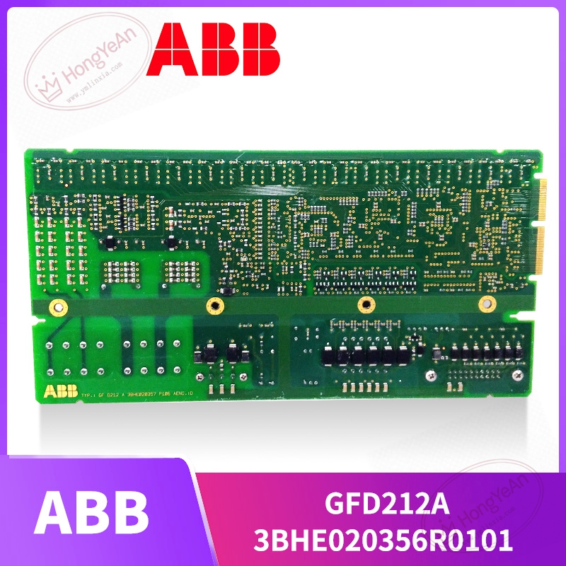
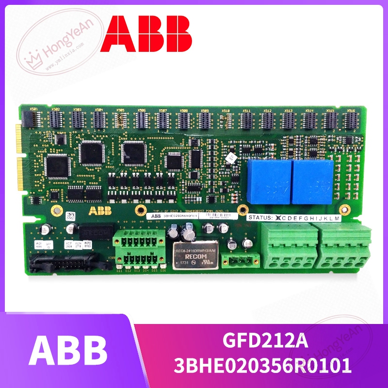
Description
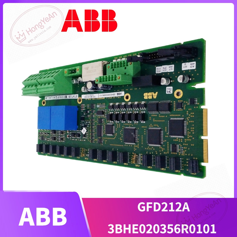
Key Technical Parameters
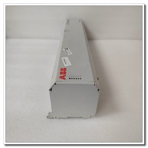
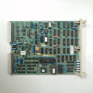
Device Type: Rack‑mount gate firing interface printed‑circuit assembly Part Codes: 3BHE020356R0101, model identifier GFD212A Signal Interface: Multiple plastic optical fiber ports for trigger output and fault feedback; system backplane bus for internal data exchange Main Task: Optical‑electrical signal conversion for thyristor / IGCT power device firing control On‑board Indication: LED group for local hardware and channel status hint Power Source: Auxiliary low‑voltage power supplied from converter internal power circuits Mechanical Structure: Standard rack plug‑in PCB, ESD protection required during handling Operating Ambient Temperature: 0℃ ~ +55℃, non‑condensing inside control cabinet Storage Temperature:‑40℃ ~ +70℃ for spare‑part preservation Compatible Systems: ABB UNITROL excitation equipment, medium‑voltage converter and SVG static var compensator hardware Important Note: Cannot run on its own. Must be matched with complete control rack and gate‑drive units. Hot‑swap under live voltage is forbidden. Hardware revision and firmware need to align with original system configuration.
Practical Application Features
Converts electrical control signals from main controller into optical firing pulses, to drive power semiconductor switching actions. Receives fault feedback signals from power unit side, and transmits abnormality information back to upper‑level control logic. Optical fiber transmission effectively suppresses heavy electromagnetic interference existing inside high‑power converter cabinets. Built‑in hardware diagnosis can capture circuit anomalies and assist technicians with on‑site troubleshooting work. Compact plug‑in design supports convenient disassembly and assembly during overhaul work. Common usage scenarios: generator excitation cabinets for thermal‑power and hydropower plants, SVG static var compensator units, medium‑voltage converter for large‑pump and fan sets, replacement parts for aging power‑electronic control cabinets.
Field Installation & Commissioning Guidance
Cut off both high‑voltage and auxiliary low‑voltage power supply before removing or fitting this board. Follow high‑voltage safety operation rules strictly. Insert the board into designated rack slot and lock securely to guarantee stable back‑plane contact. Distinguish trigger‑output optical fiber and fault‑feedback optical fiber, avoid mis‑insertion. Maintain required minimum bending radius to prevent fiber breakage and optical attenuation. Check auxiliary power wiring condition. Visually inspect PCB surface for scratches, burnt components and abnormal solder joints before power‑on. Complete system configuration via dedicated engineering software, confirm firmware consistency between this interface board and other control components. Perform low‑voltage pre‑test without high‑voltage power: verify LED indication, optical signal transmit‑receive performance and fault feedback logic. Proceed step‑by‑step high‑voltage power‑on test after low‑voltage test passes. Observe equipment running status and monitor fault‑related diagnostic variables. Keep cabinet internal heat‑dissipation in good condition. Avoid long‑time continuous operation under excessive ambient temperature, which accelerates aging of on‑board electrolytic capacitors.
In‑Site Troubleshooting Reference
- Board LED indicators stay dark: Check auxiliary power supply loop, terminal tightening condition or internal power‑circuit damage on PCB.
- Main controller reports firing‑channel fault: Inspect optical fiber for breakage, sharp bending or dirty end‑faces; clean or replace optical fiber; check power‑semiconductor device status.
- Intermittent fault alarms: Unqualified back‑plane contact, cabinet overtemperature, severe on‑site electromagnetic interference. Re‑lock module and improve cabinet ventilation and grounding.
- Power device fails to respond to firing command: Distinguish root cause among this interface board fault, gate‑drive unit damage or power‑chip breakdown; separate inspection is required.
- Module cannot be recognized by system: Improper slot position, contamination on back‑plane pins, hardware revision mismatch with original configuration.
- Board damaged after equipment short‑circuit accident: High‑voltage surge invades signal loop. Replace this interface board, meanwhile check whether matched power‑semiconductor and gate‑drive hardware suffer secondary damage.
-300x300.jpg)
Reviews
There are no reviews yet.