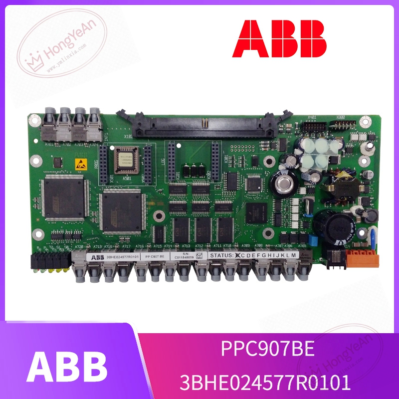
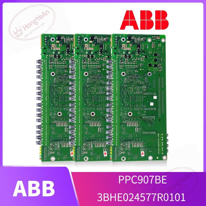
Description
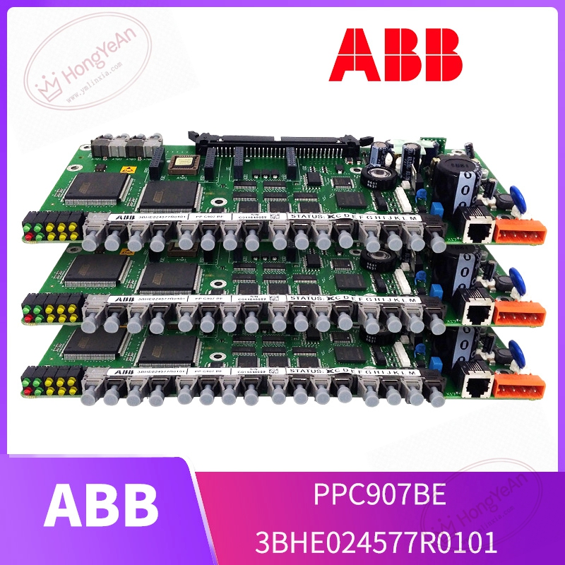
Key Technical Parameters
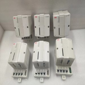
Device Type: Rack‑mount plug‑in high‑speed processor board Part Codes: 3BHE024577R0101, PPC907BE Core hardware: High‑performance real‑time processing chip for power‑electronic algorithm calculation Memory: On‑board RAM for runtime variables; Flash storage for firmware and application logic Interfaces: Multiple optical and electrical communication ports; backplane bus for rack‑internal data exchange Power supply: Auxiliary low‑voltage power fed from converter rack power circuit Status indication: Multi‑LED indicators for running state, hardware fault and communication diagnostics Operating ambient temperature: ‑25℃ ~ +70℃, non‑condensing inside cabinet Storage temperature:‑40℃ ~ +85℃ for spare‑part storage Mechanical feature: Metal‑shielded plug‑in structure, IP20 rating for indoor cabinet installation Compatible hardware: Matched with ABB excitation controllers, SVG static var compensators and medium‑voltage converter racks Important Note: Cannot operate independently. Must cooperate with matched backplane, peripheral boards and auxiliary power supply. Firmware revision needs to align with whole system. Live‑plug‑out is strictly forbidden.
Practical Application Features
Executes high‑speed closed‑loop regulation for voltage and current, completes real‑time computation tasks for power conversion equipment. Handles data interaction with peripheral I/O boards and gate‑drive assemblies, receives fault feedback from power semiconductor devices. Built‑in diagnosis function captures hardware and communication abnormalities, and records fault snapshot data for post‑event analysis. Optical‑isolation and metal‑shielding structure improves anti‑interference performance under harsh electromagnetic environment inside high‑voltage cabinets. Supports parameter downloading, debugging and status viewing via dedicated engineering tool. Common real‑world scenarios: generator excitation control in thermal‑power and hydropower plants, SVG static var compensation units, medium‑voltage drives for large‑pump and fan sets, component replacement for aging power‑electronic control cabinets.
Field Installation & Commissioning Guidance
Disconnect all high‑voltage and auxiliary low‑voltage power before disassembly or fitting. Strictly follow high‑voltage safety operation procedures. Insert the processor board into the designated rack slot and lock firmly to guarantee stable backplane contact. Differentiate optical fibers for command output and fault feedback to avoid mis‑connection; maintain required minimum bending radius to prevent fiber breakage and optical attenuation. Check auxiliary power wiring and terminal tightening condition. Visually inspect PCB for scratches, burnt components and abnormal solder joints before power‑on. Download matched firmware and application logic through ABB dedicated engineering software. Confirm firmware consistency between this processor and peripheral hardware. Complete low‑voltage pre‑test without high‑voltage power: verify LED running status, optical transmit‑receive performance and fault feedback logic. Proceed step‑by‑step high‑voltage power‑on test after low‑voltage test passes. Monitor real‑time operating variables and fault‑alarm information. Ensure good cabinet heat‑dissipation. Avoid long‑time continuous operation under excessive ambient temperature to slow down aging of on‑board electrolytic capacitors.
In‑Site Troubleshooting Reference
- All front‑panel LEDs stay off: Check auxiliary power supply loop, loose terminals and internal power‑circuit damage on PCB.
- System reports processor communication failure: Inspect backplane contact; check optical fiber breakage or contaminated fiber end‑face; confirm firmware‑version matching.
- Converter trips frequently during operation: Export fault snapshot records, distinguish faults caused by this processor itself or peripheral gate‑drive / power‑semiconductor failure; verify control‑parameter setting.
- Intermittent random fault alarms: Poor cabinet shielding‑grounding, cabinet overtemperature, severe on‑site electromagnetic interference. Improve ventilation and grounding condition.
- Fail to download firmware or application project: Mismatched engineering‑tool version; backplane‑bus communication anomaly; hardware damage of on‑board Flash chip.
- Board damaged after short‑circuit accident: High‑voltage surge invades control loop. Replace this processor unit, meanwhile inspect gate‑drive boards and power chips for secondary damage.
-300x300.jpg)
Reviews
There are no reviews yet.