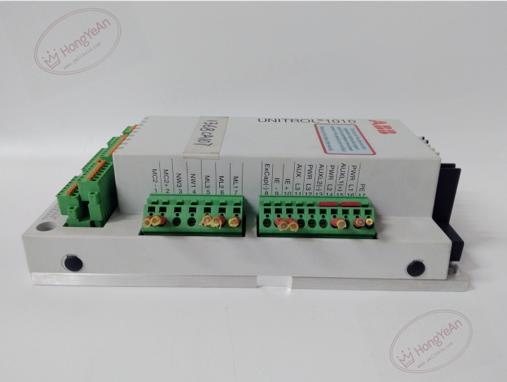
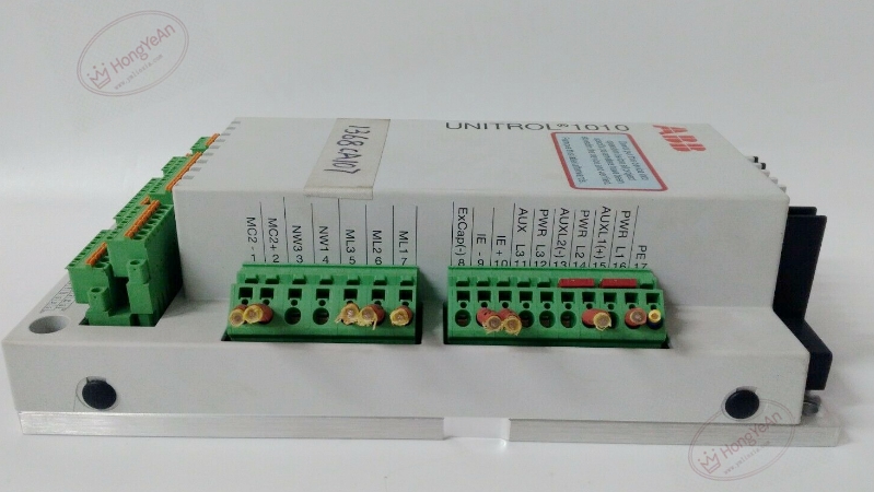
Description
Hardware & Electrical Specifications
‑ Manufacturer: ABB ‑ Compatible System: UNITROL 1010 generator excitation system ‑ Functional Type: Digital Excitation Controller / AVR ‑ Main Power Input: Three‑phase excitation power input; auxiliary AC supply ‑ Regulation Accuracy: ±0.5 % for generator terminal voltage ‑ Control Modes: Automatic voltage regulation, reactive power / power‑factor control, manual excitation current control ‑ I/O: Analog measurement inputs for generator voltage, current; discrete interlock inputs, relay alarm & trip outputs ‑ Communication Interfaces: RS232, RS485, Ethernet; supports Modbus TCP, Modbus RTU, IEC 61850 protocols ‑ Configuration Tool: CMT1000 software (firmware Release 6.31) ‑ Data Recording: Stores historical fault events and disturbance records for post‑fault analysis ‑ Connectors: Screw terminal blocks for power, measurement, field I/O and communication ‑ Mounting: Cabinet panel‑mount installation ‑ PCB Finish: Conformal coated for power‑plant harsh environment
Environmental Specifications
‑ Operating Temperature: ‑20 °C ~ +60 °C ‑ Storage Temperature: ‑40 °C ~ +85 °C ‑ Relative Humidity: 5 %‑95 % non‑condensing ‑ Vibration & Shock: Complies with IEC standards for power‑generation cabinet EMI and transient conditions
Mechanical Data
‑ Weight: approx 2.9 kg
Core Functions
- Generator voltage regulation: High‑speed digital AVR adjusts excitation current to stabilize generator terminal voltage under grid‑connected or island operation.
- Reactive power / power‑factor control: Supports reactive power set‑point control for grid‑compliant generator operation.
- Integrated limit and protection: Over‑excitation, under‑excitation, V/Hz, rotor over‑current and loss‑of‑excitation protection functions.
- System interlock & alarm: Processes external interlock signals; outputs relay alarms for excitation‑system faults to DCS and local annunciator.
- Communication & diagnostics: Uploads real‑time generator and excitation parameters to plant DCS; stores fault sequence records for maintenance troubleshooting.
Installation, Replacement & Critical Warnings
- De‑energize all AC power and generator field circuits before replacement. This unit is non‑hot‑swappable. Generator high‑voltage hazards exist on measurement and power terminals.
- After hardware replacement, download matching project parameters via CMT1000 tool; default factory parameters cannot be used for field operation.
- Torque all power‑circuit and signal‑circuit screw terminals; loose terminals cause voltage measurement distortion and unstable excitation regulation.
- After installation, complete static test, no‑load generator test and grid‑paralleling commissioning step‑by‑step. Verify regulation, limit and protection functions.
-
Common failure mode: Surge damage to measurement input circuits, power‑section component aging. Investigate PT/CT secondary‑side faults when abnormal voltage or excitation‑current alarms occur.
-300x300.jpg)
Reviews
There are no reviews yet.