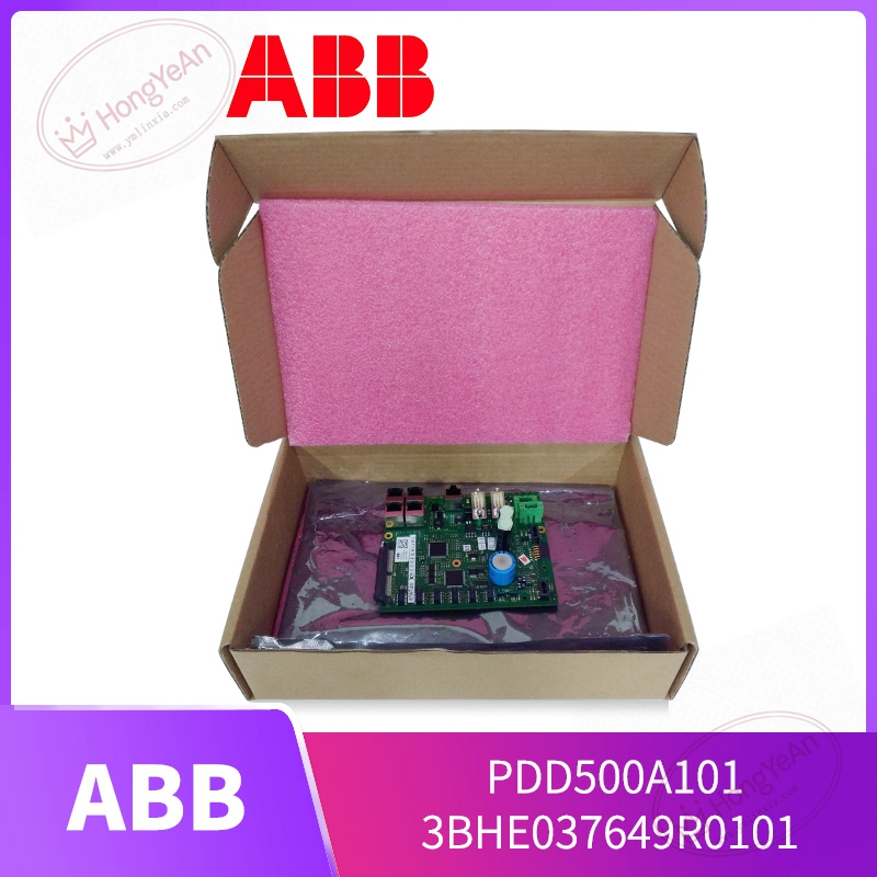
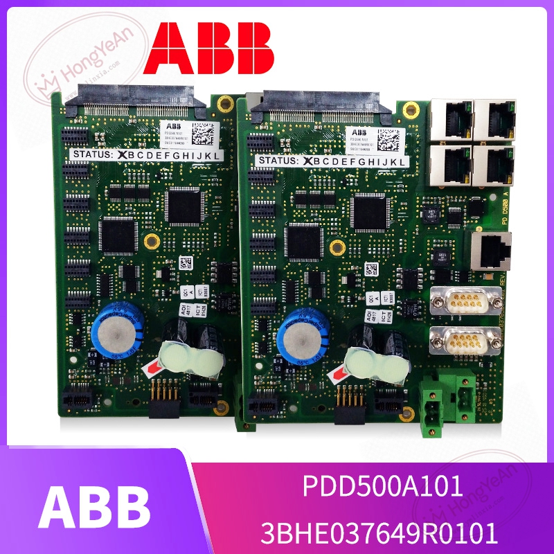
Description
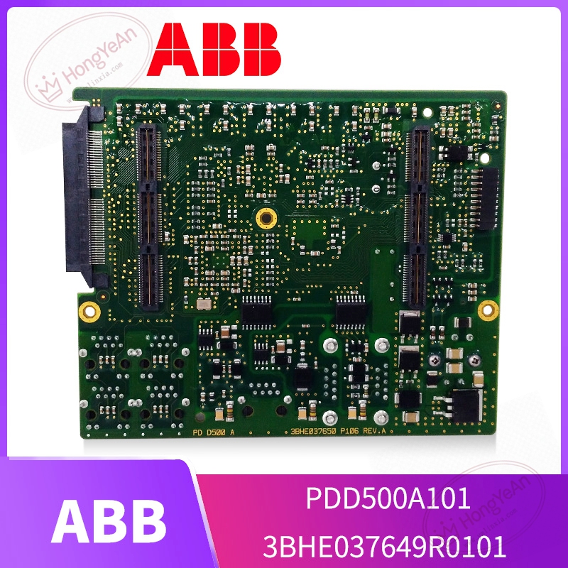
Key Technical Parameters
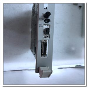
Device Type: Rack‑mount plug‑in drive processing board Part Codes: 3BHE037649R0101, PDD500A101 Core Unit: High‑speed real‑time processing chip for power‑electronic algorithm Memory: On‑board Flash for firmware storage, RAM for runtime variable cache Interfaces: Multiple optical fiber ports for power‑device trigger and fault feedback; backplane bus for rack‑internal data interaction Power Requirement: Auxiliary low‑voltage power supplied from converter internal power unit Status Indication: Multi‑LED indicators for running status, hardware fault and communication diagnosis Operating Ambient Temperature: ‑25℃ ~ +70℃, non‑condensing inside control cabinet Storage Temperature:‑40℃ ~ +85℃ Mechanical: Metal‑shielded plug‑in structure, IP20 protection for cabinet‑installation only Compatible Systems: ABB UNITROL excitation system, SVG static var compensator, medium‑voltage converter control racks Important Note: Cannot work independently. Needs matched backplane, gate‑drive hardware and auxiliary power supply. Firmware version must keep consistent with whole system. Hot‑swap under live condition is forbidden.
Practical Application Features
Executes fast current‑loop and voltage‑loop closed‑loop calculation, generates optical trigger commands for IGBT / IGCT power stacks. Receives fault feedback signals from peripheral gate drive boards, supports rapid over‑current, over‑voltage and over‑temperature protection responses. Built‑in fault snapshot recording function, stores key operating data when abnormality occurs for later maintenance analysis. Optical‑isolation plus metal shielding housing effectively suppresses strong electromagnetic noise inside high‑power converter cabinets. Supports parameter configuration, debugging and status checking via dedicated ABB engineering software. Common usage scenarios: thermal‑hydropower generator excitation cabinets, SVG static var compensation units, medium‑voltage high‑power converters for fans, pumps and rolling mills, component renewal for legacy power‑electronic control cabinets.
Field Installation & Commissioning Guidance
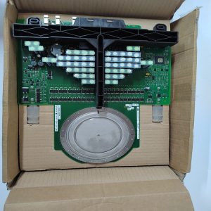
Cut off all high‑voltage and auxiliary low‑voltage power before installation or removal, strictly comply with high‑voltage safety operation specifications. Insert the drive processing board into designated rack slot and lock tightly to guarantee stable backplane contact. Distinguish optical fiber for command output and fault feedback to avoid mis‑connection; keep enough bending radius to prevent fiber breakage and optical‑signal attenuation. Check auxiliary power‑supply terminals are well tightened. Visually inspect PCB for scratches, burnt‑out components and abnormal solder joints before power‑on. Download matched firmware and application logic through special engineering tool. Confirm firmware consistency between this board and peripheral gate‑drive assemblies. Perform low‑voltage pre‑test without high‑voltage power supply: verify LED status, optical transmit‑receive performance and fault feedback logic. Conduct step‑by‑step high‑voltage power‑on test after low‑voltage test passes. Keep tracking real‑time operating variables and fault‑alarm messages. Maintain good cabinet heat‑dissipation performance. Avoid long‑time continuous operation under over‑temperature environment to slow down aging of on‑board electrolytic capacitors.
In‑Site Troubleshooting Reference
- All front‑panel LEDs remain dark: Check auxiliary power‑supply loop, loose terminals or internal power‑circuit damage on PCB.
- System reports board communication fault: Inspect backplane contact condition; check optical fiber damage or dirt on fiber end‑face; confirm firmware‑version matching.
- Converter triggers frequent trips: Export fault snapshot records, judge whether fault comes from this processing board itself or peripheral gate‑drive / power‑semiconductor failure; double‑check control‑parameter settings.
- Intermittent random fault alarms: Poor cabinet shielding‑grounding, cabinet inner overtemperature, severe electromagnetic interference. Optimize ventilation and grounding treatment.
- Fail to download firmware or application project: Mismatched engineering‑tool version; backplane bus communication anomaly; hardware damage of on‑board Flash chip.
- Board damaged after short‑circuit accident: High‑voltage surge invades control loop. Replace this drive processing board, meanwhile inspect gate‑drive boards and power chips for secondary damage.
-300x300.jpg)
Reviews
There are no reviews yet.