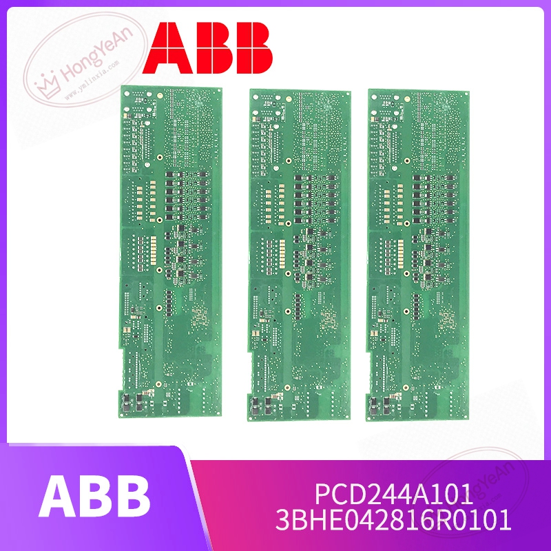
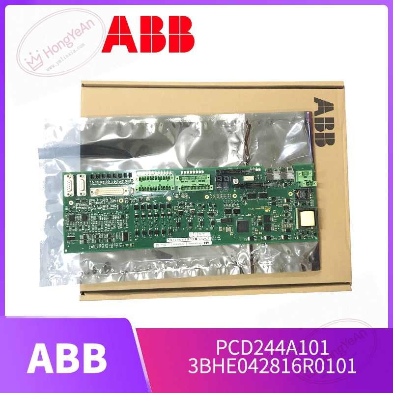
Description
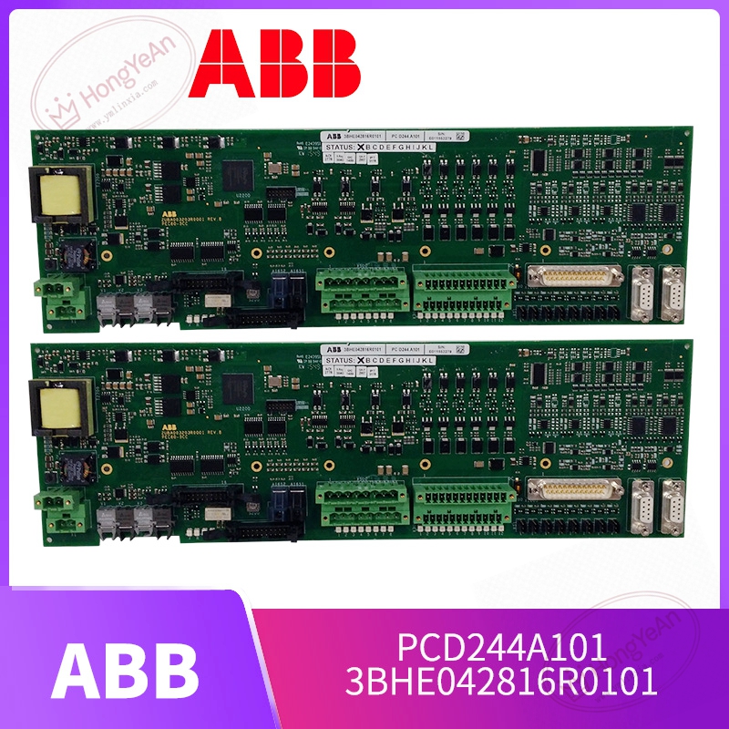
Key Technical Parameters
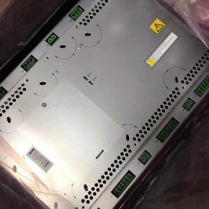
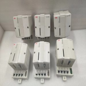
Device Type: Rack‑mount signal processing control board Part Codes: 3BHE042816R0101, PCD244A101 Core function: Multi‑channel signal sampling, data conditioning and internal system data interaction Interfaces: Backplane bus for rack‑internal communication; multiple signal input channels for field equipment connection Memory: On‑board Flash for parameter storage, RAM for real‑time data buffering Power supply: Auxiliary low‑voltage power supplied from converter control rack Status Indication: LED lights for module running status and hardware fault prompting Operating Ambient Temperature: ‑25℃ ~ +70℃, non‑condensing inside cabinet Storage Temperature:‑40℃ ~ +85℃ for spare‑part storage Mechanical: Standard plug‑in PCB assembly, ESD protection required during handling Compatible System: ABB UNITROL excitation system, SVG static var compensator, PEC series medium‑voltage control racks Important Note: Cannot run independently. Must match corresponding rack and related control hardware. Hot‑swap under live voltage is not allowed. Parameter and firmware revision should keep consistent with original system.
Practical Application Features
Samples and conditions various analog and digital signals from field‑side equipment, transmits processed valid data to main controller for closed‑loop calculation. Built‑in hardware diagnosis mechanism can detect channel abnormality and circuit failure, upload alarm information to upper monitoring system. Industrial‑grade circuit design improves anti‑interference ability under complex electromagnetic environment inside power‑electronic cabinets. Compact plug‑in structure supports convenient disassembly and inspection for routine maintenance and fault location. Common usage scenarios: generator excitation cabinets for thermal‑power and hydropower plants, static var compensation control units, medium‑voltage converter assemblies for large‑scale pumps and fans, component replacement for long‑term operated legacy automation cabinets.
Field Installation & Commissioning Guidance
Disconnect all high‑voltage and auxiliary low‑voltage power before installation or removal, strictly follow industrial high‑voltage safety operation rules. Insert the board into designated rack slot and lock securely to guarantee stable backplane pin contact. Arrange field signal cables reasonably, keep signal wiring separated from high‑power cables to reduce electromagnetic interference. Visually check PCB surface for scratches, burnt‑out components and abnormal solder joints before power‑on. Complete hardware configuration through dedicated engineering software, confirm firmware matching between this board and other control components of the whole system. Restore power supply step‑by‑step, observe LED status, make sure no hardware fault alarm appears. Carry out channel point‑to‑point test, verify signal acquisition and data transmission performance. Keep cabinet ventilation in good condition. Avoid long‑time continuous operation under excessive ambient temperature to prevent premature aging of on‑board electronic components.
In‑Site Troubleshooting Reference
- All LED indicators stay off: Check rack auxiliary power‑supply loop, terminal tightening condition or internal power‑circuit damage on PCB.
- System reports module communication failure: Inspect backplane contact condition, check pin contamination; confirm firmware‑version consistency of whole system.
- Partial channel data reading deviation or invalid: Field‑side signal loop open‑circuit / short‑circuit; loose terminal connection; internal channel circuit damage on this board.
- Intermittent signal jumping or data loss: Poor cabinet shielding‑grounding; signal cables mixed with high‑power wiring; cabinet inner overtemperature. Optimize grounding and heat‑dissipation environment.
- Module cannot be identified by host controller: Improper slot position; incomplete system configuration download; backplane bus communication abnormality.
- Board damaged after site short‑circuit accident: Voltage surge invades signal loop. Replace this signal processing board, meanwhile check other associated control hardware for secondary damage.
-300x300.jpg)
Reviews
There are no reviews yet.