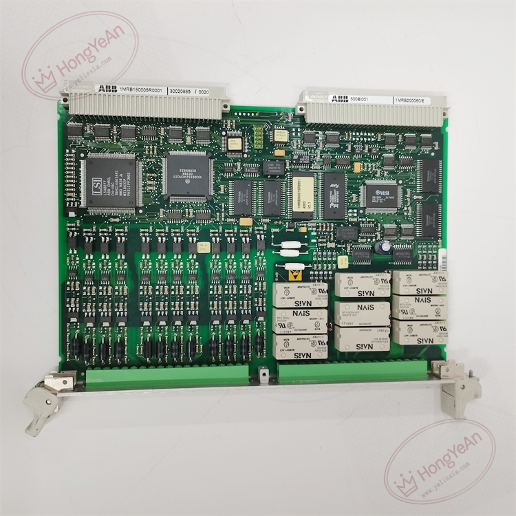
Description
‑ Power Supply: Powered by Procontrol P13 rack back‑plane bus; field side 24 VDC
‑ Power Consumption: approx 5 W (depends on output load)
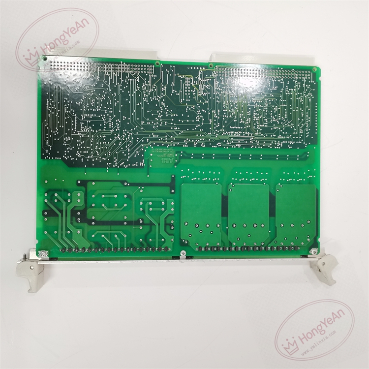
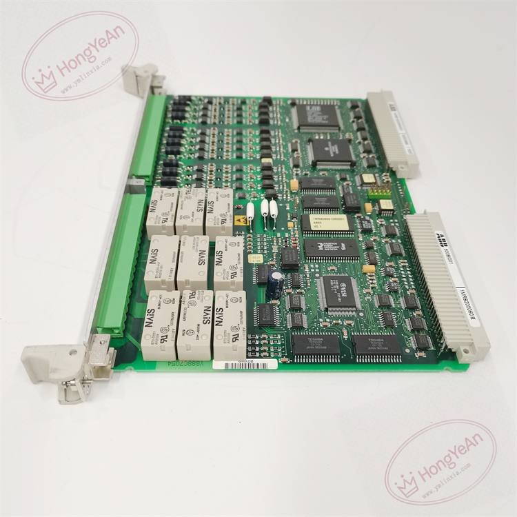
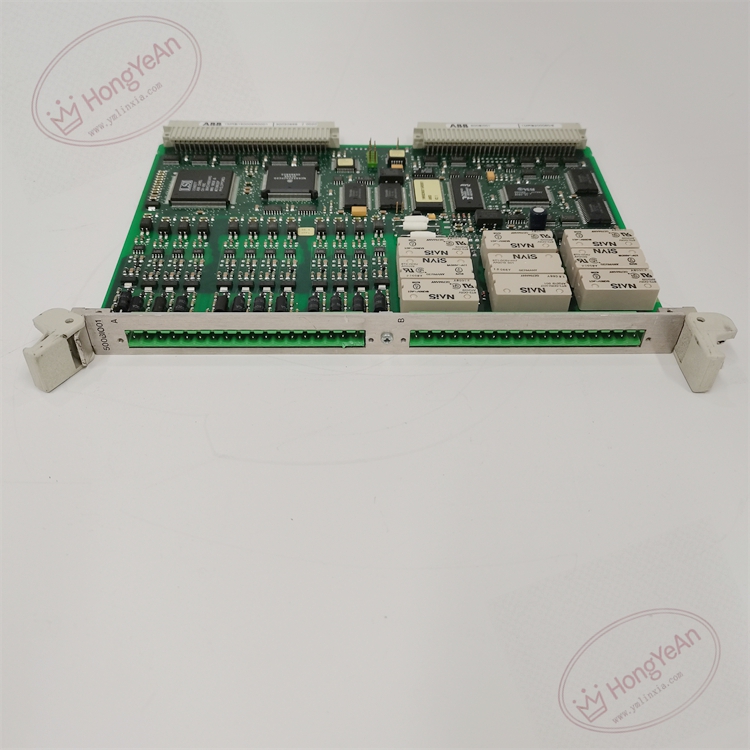
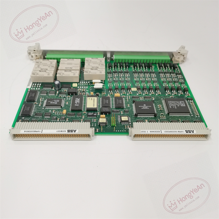
‑ Mechanical Structure: Eurocard plug‑in board for Procontrol P13 rack, metal front panel, back‑plane bus connector, field signal terminal connector
‑ On‑board Resources: Multi‑channel signal conditioning circuit, opto‑coupler isolation circuit, input debounce filter, output driving circuit, channel diagnosis logic, back‑plane bus interface, module self‑diagnosis unit
‑ Communication Interface: Internal dedicated back‑plane bus for data interaction with system CPU
‑ Galvanic Isolation: Galvanic isolation between field channels and internal logic bus, isolation rating 2500 VAC
‑ Signal Level: 24 VDC nominal for input and output
‑ Number of Channels: total 16 configurable binary channels, software‑selectable DI or DO
‑ Input Characteristic: logic 0 ≤13 V DC; logic 1 ≥18 V DC
‑ Output Characteristic: each channel max 500 mA, short‑circuit protected
‑ Input Filter Time: configurable hardware debounce
‑ Status LED Indicators: Power indicator, Module Fault indicator, per‑channel status LED
‑ Weight: approx 0.95 kg
‑ Multi‑purpose 16‑channel binary I/O, each channel software configurable as binary input or binary output.
‑ As input: collects breaker position, isolating‑switch status, interlock contact and alarm contact signals; hardware debounce filtering suppresses contact bounce and field electromagnetic interference.
‑ As output: receives control commands from CPU, drives field relays, indicator lamps and small‑power 24 VDC actuators; output channel supports short‑circuit and overload protection.
‑ Channel‑level diagnosis: input wire‑break detection, output short‑circuit / overload fault detection, reports channel fault status to main processor.
‑ Transmits binary input status, output feedback and channel diagnostic information to system CPU through back‑plane bus.
‑ Module self‑diagnosis detects power‑supply deviation, internal circuit failure and back‑plane bus communication fault, uploads fault alarm information.
‑ Cannot work independently; must be installed inside Procontrol P13 rack and cooperate with CPU, power‑supply and other rack modules. 1MRB150005R0001 is hardware variant of 500BIO01 series; pin‑compatible within 500BIO01 revision family, cannot be directly interchanged with other series I/O boards.
‑ Continuously monitors input channel condition, output load state, module power‑supply and internal hardware health. Detected faults activate fault LED and send fault word to main CPU.
‑ No local numerical display; binary status, channel alarms and fault codes are read via commissioning software or upper‑level HMI workstation.
‑ Module hardware failure leads to loss of related channels input acquisition and output control; other system functions remain normal if CPU and power‑supply work properly.
‑ Back‑plane connector: connects to Procontrol P13 internal back‑plane bus for data exchange with CPU and other plug‑in modules.
‑ Field signal terminal connector: connection terminal for field binary contact and actuator wiring.
‑ Mounting: Plug‑in installation inside Procontrol P13 system rack
‑ Operating Temperature: ‑20 °C ~ +60 °C
‑ Storage Temperature: −40 °C ~ +70 °C
‑ Relative Humidity: 5‑95 %RH, non‑condensing
‑ Protection Class: IP20 (cabinet internal)
- 500BIO01 binary input‑output combined module (1MRB150005R0001)
Complementary parts: Procontrol P13 rack and back‑plane, system CPU module, rack power‑supply unit, field shielded signal cables, Procontrol P13 commissioning software.
‑ Power off the whole rack before inserting or removing this I/O module. Field signal wiring shall adopt shielded cables with single‑end shield grounding to restrain electromagnetic interference.
‑ For spare‑part replacement: Verify complete part number 1MRB150005R0001. After replacement, confirm back‑plane bus identification, download channel configuration parameters, verify binary‑signal acquisition, output drive and channel fault‑reporting function.
‑ Module hardware fault will cause loss of input‑output function for associated channels.
Generator‑transformer control cabinets of thermal / hydro power plants; ABB Procontrol P13 automation system; industrial spare‑part replacement for mixed binary input‑output signal processing.
- Procontrol P13 platform configurable combined binary I/O module, total 16 channels, each channel software‑selectable DI / DO, saving rack slot resources.
- Built‑in channel‑level fault diagnosis for input wire‑break and output short‑circuit overload, convenient for field fault locating.
- Galvanic isolation between field side and internal logic bus, good anti‑interference performance for power‑plant harsh electromagnetic environment.
- Input supports hardware debounce filtering; output carries short‑circuit protection, transmits channel status and diagnostic status to main processor over back‑plane bus.
- Standard Eurocard rack‑mount plug‑in structure, easy installation and on‑site maintenance.
Reviews
There are no reviews yet.