Description
‑ Power Supply: Powered by Procontrol P13 rack back‑plane bus; field load 24 VDC external power supply
‑ Power Consumption: approx 6 W (power consumption rises with load current)
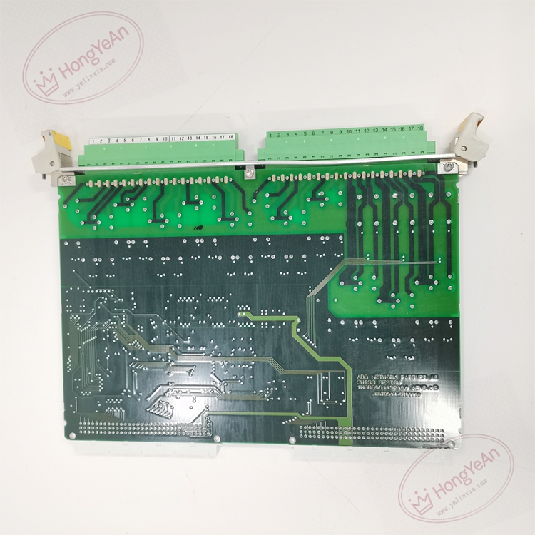
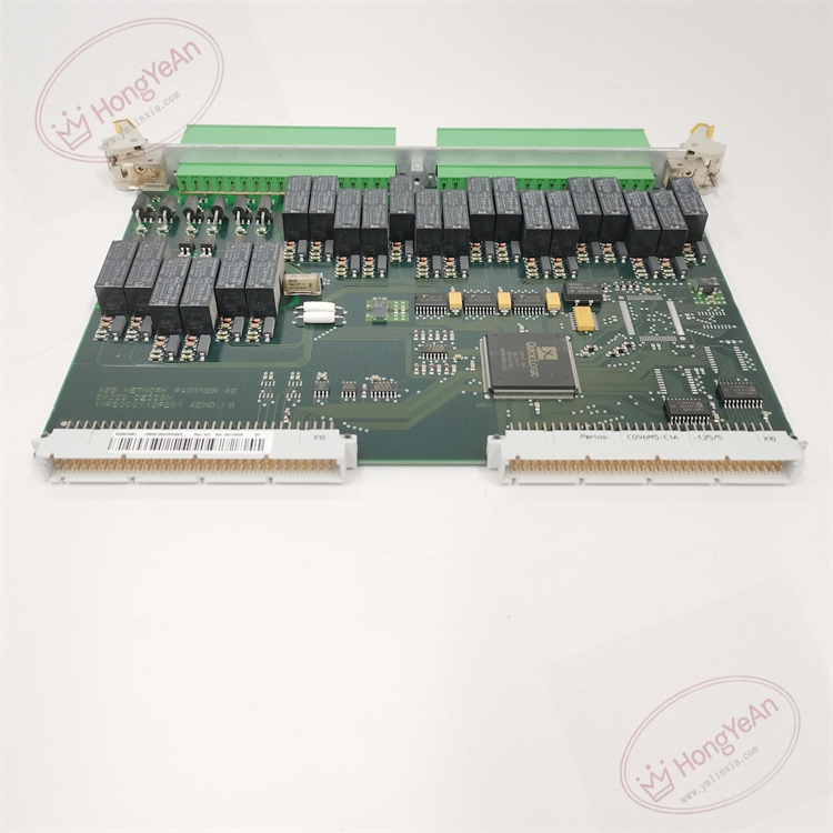
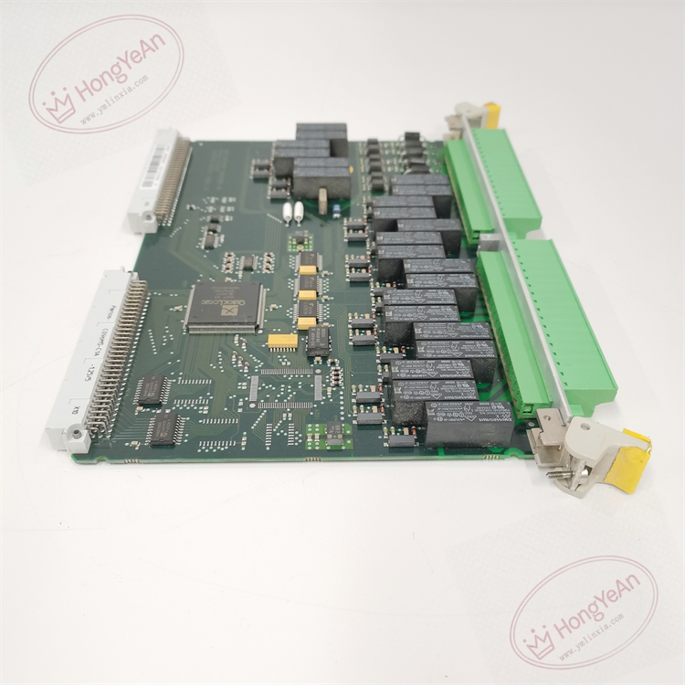
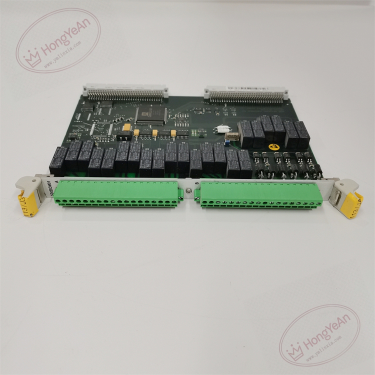
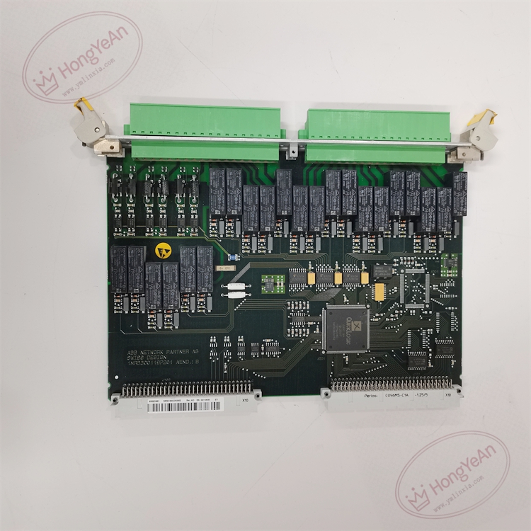
‑ Mechanical Structure: Eurocard plug‑in board for Procontrol P13 rack, metal front panel, back‑plane bus connector, field signal terminal connector
‑ On‑board Resources: Back‑plane bus interface, command decoding logic, output driving circuit, short‑circuit and overload protection circuit, channel diagnosis unit, module self‑diagnosis circuit
‑ Communication Interface: Internal dedicated back‑plane bus for data interaction with system CPU
‑ Galvanic Isolation: Galvanic isolation between field output channels and internal logic bus, isolation rating 2500 VAC
‑ Output Signal Type: 24 VDC active level output
‑ Number of Channels: 16 binary output channels
‑ Single‑channel rated output current: max 500 mA
‑ Protection: Each channel independent short‑circuit, overload protection
‑ Status LED Indicators: Power indicator, Module Fault indicator, per‑channel output status LED
‑ Weight: approx 0.95 kg
‑ Receives control commands issued by system main CPU, drives field‑side 24 VDC loads such as relays, signal lamps and small‑size contactor coils.
‑ Each output channel is provided with independent short‑circuit and overload hardware protection, preventing module damage caused by field wiring fault.
‑ Channel‑level diagnosis: detects output overload, short‑circuit and load abnormal state, reports channel fault information to main processor.
‑ Feeds back actual output state and channel diagnostic data to CPU through rack back‑plane bus.
‑ Module self‑diagnosis monitors rack power‑supply, internal circuit state and back‑plane bus communication, uploads module‑level fault alarm.
‑ Cannot run independently; must be installed inside Procontrol P13 rack and cooperate with CPU, power‑supply and other functional modules. 1MRB150023R0002 is hardware variant of 500BOM01 series; pin‑compatible within 500BOM01 revision family, cannot be directly interchanged with other series I/O boards.
‑ Continuously monitors output channel load condition, module power‑supply and internal hardware health. Detected faults activate fault LED and send fault word to main CPU.
‑ No local numerical display; output status, channel alarms and fault codes are read via commissioning software or upper‑level HMI workstation.
‑ Module hardware failure leads to loss of control capability on corresponding output channels; other system functions remain normal if CPU and power‑supply work properly.
‑ Back‑plane connector: connects to Procontrol P13 internal back‑plane bus for data exchange with CPU and other plug‑in modules.
‑ Field signal terminal connector: wiring terminal for field actuators and load equipment.
‑ Mounting: Plug‑in installation inside Procontrol P13 system rack
‑ Operating Temperature: ‑20 °C ~ +60 °C
‑ Storage Temperature: −40 °C ~ +70 °C
‑ Relative Humidity: 5‑95 %RH, non‑condensing
‑ Protection Class: IP20 (cabinet internal)
- 500BOM01 binary output module (1MRB150023R0002)
Complementary parts: Procontrol P13 rack and back‑plane, system CPU module, rack power‑supply unit, field shielded signal cables, Procontrol P13 commissioning software.
‑ Power off the whole rack before inserting or removing this binary output module. Field load wiring shall adopt shielded cables with single‑end shield grounding to restrain electromagnetic interference. Pay attention to the total load current of module, shall not exceed rated value.
‑ For spare‑part replacement: Verify complete part number 1MRB150023R0002. After replacement, confirm back‑plane bus identification, download channel configuration parameters, verify output drive function and channel fault‑reporting function.
‑ Module hardware fault will cause loss of control output for associated channels.
Generator‑transformer control cabinets of thermal / hydro power plants; ABB Procontrol P13 automation system; industrial spare‑part replacement for binary control output channels.
- Procontrol P13 platform high‑density binary output module, 16 channels 24 VDC driving output, each channel with independent short‑circuit and overload protection.
- Built‑in channel‑level fault diagnosis for overload and short‑circuit, convenient for field fault locating.
- Galvanic isolation between field side and internal logic bus, good anti‑interference performance for power‑plant harsh electromagnetic environment.
- Receives control commands from CPU, feeds back output status and diagnostic information over back‑plane bus.
- Standard Eurocard rack‑mount plug‑in structure, easy installation and on‑site maintenance.
-300x300.jpg)
Reviews
There are no reviews yet.