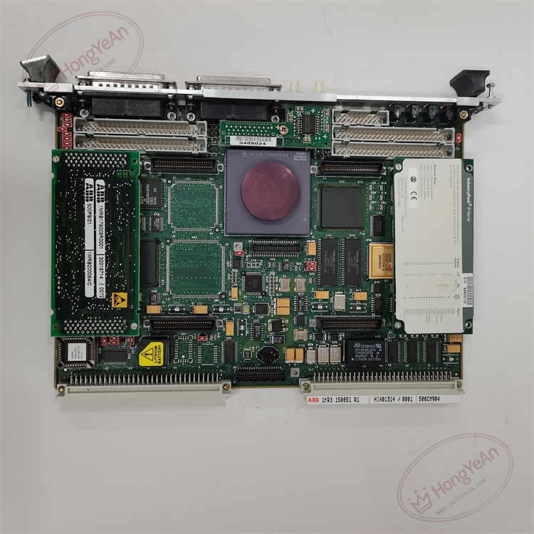
Description
‑ Power Supply: Powered by Procontrol P13 rack back‑plane bus
‑ Power Consumption: approx 14 W
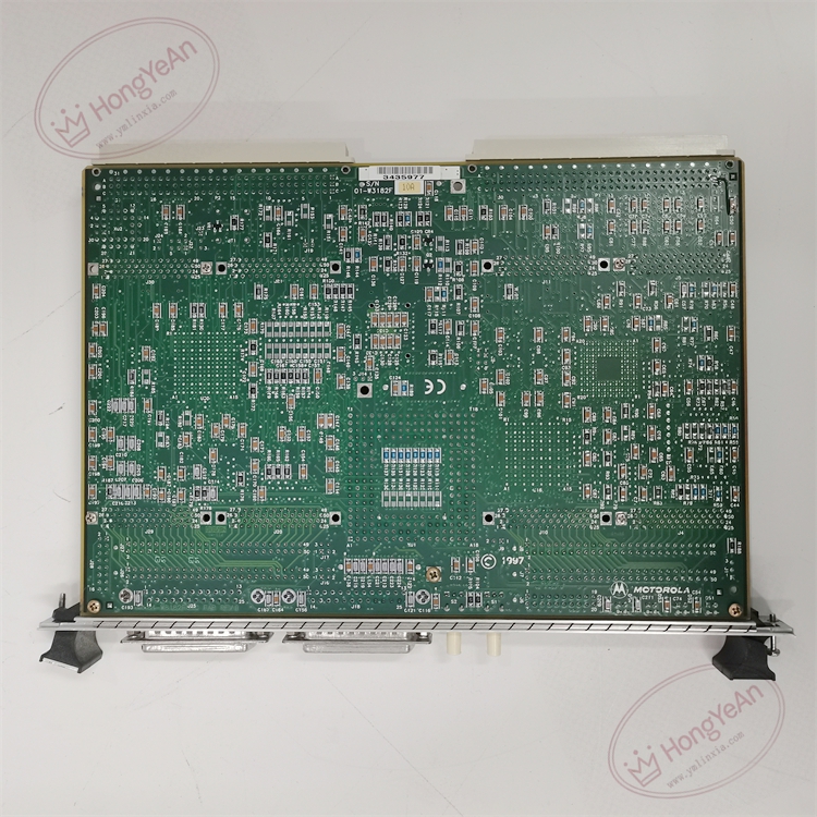
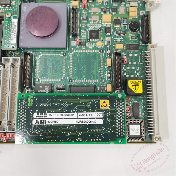
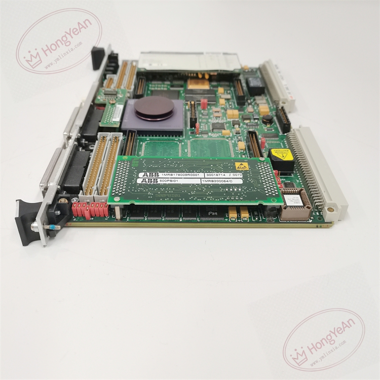
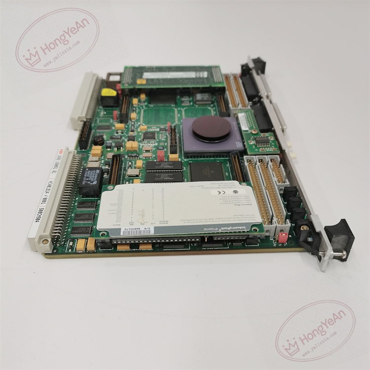
‑ Mechanical Structure: Eurocard plug‑in board for Procontrol P13 rack, metal front panel, back‑plane bus connector, front‑panel service debug interface
‑ On‑board Resources: 32‑bit industrial processor, program Flash memory, data RAM, real‑time clock circuit, back‑plane bus controller, module self‑diagnosis unit, event log storage unit
‑ Communication Interface: Internal dedicated local back‑plane bus for I/O modules; front‑panel service serial port for commissioning and debugging
‑ Galvanic Isolation: Galvanic isolation for service debug port
‑ Status LED Indicators: Power indicator, Run indicator, Module Fault indicator, bus communication status LEDs
‑ Weight: approx 1.15 kg
‑ Real‑time cyclic execution of Procontrol P13 control application logic, completes interlock, sequence control and closed‑loop calculation for power‑plant process.
‑ Collects measurement values and channel diagnostic status from analog input, binary input modules through rack back‑plane bus.
‑ Generates control commands according to control logic, sends commands to binary output and other output modules to drive field actuators.
‑ Stores process events, fault alarm records, supports time‑stamped event logging.
‑ Cooperates with communication module to realize data exchange with upper‑level HMI, remote bay units; supports program download, parameter configuration via commissioning tool.
‑ Comprehensive module self‑diagnosis: monitors processor running state, memory check, power‑supply deviation, back‑plane bus communication fault, uploads fault alarm information.
‑ Can adopt redundant dual‑module hot‑standby configuration to improve system availability. 1MRB150051R1 is hardware revision of 500CMP04 series; must match corresponding application firmware, pin‑compatible within 500CMP04 revision family, cannot directly interchange with other series processor boards.
‑ Continuously monitors processor operation, memory integrity, back‑plane bus communication and module power‑supply health. Detected faults activate fault LED and send fault word to system diagnosis.
‑ No local numerical display; control state, alarm events and fault codes are read via commissioning software or upper‑level HMI workstation.
‑ Module hardware failure will cause the whole rack control logic to stop running; redundant configuration will automatically switch to standby processor.
‑ Back‑plane connector: connects to Procontrol P13 internal local bus for data exchange with I/O modules and communication modules.
‑ Front‑panel service port: serial debug interface for on‑site commissioning, program download and fault diagnosis.
‑ Mounting: Plug‑in installation inside Procontrol P13 system rack
‑ Operating Temperature: ‑20 °C ~ +60 °C
‑ Storage Temperature: −40 °C ~ +70 °C
‑ Relative Humidity: 5‑95 %RH, non‑condensing
‑ Protection Class: IP20 (cabinet internal)
- 500CMP04 central processor module (1MRB150051R1)
Complementary parts: Procontrol P13 rack and back‑plane, rack power‑supply unit, I/O modules, communication module, shielded service cables, Procontrol P13 commissioning software.
‑ Power off the whole rack before inserting or removing this processor module. Service debugging wiring adopts shielded cables with single‑end shield grounding.
‑ For spare‑part replacement: Verify complete part number 1MRB150051R1 and confirm firmware version matching requirement. After replacement, confirm back‑plane bus identification, download control program and configuration parameters, verify logic execution, event recording and fault‑reporting function. Firmware mismatch will cause system abnormal operation.
‑ Module hardware fault will lead to suspension of rack control function; redundant configuration shall verify switch‑over function after replacement.
Generator‑transformer control cabinets of thermal / hydro power plants; ABB Procontrol P13 automation system; industrial spare‑part replacement for rack main processing unit.
- Procontrol P13 rack core central processor module, executes real‑time power‑plant control and interlock logic, supports redundant hot‑standby running mode.
- Built‑in event and alarm logging with time‑stamp, convenient for post‑fault analysis.
- Complete hardware self‑diagnosis function, fast positioning of processor, memory and bus faults.
- Connects all I/O and communication modules via local back‑plane bus, realizes whole‑rack process data processing.
- Standard Eurocard rack‑mount plug‑in structure, convenient installation and on‑site maintenance.
-300x300.jpg)
Reviews
There are no reviews yet.