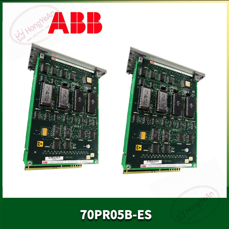
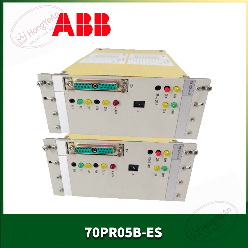
Description
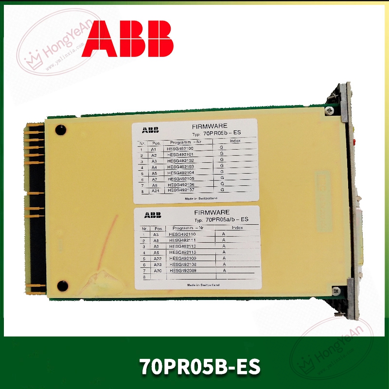
Key Technical Parameters
Device Type: Rack‑mount plug‑in processor unit Part No: 70PR05B‑ES, material code HESG332204R0001 Designed for Procontrol P13 / P14 rack framework Memory configuration includes flash storage for firmware and battery‑backed RAM for runtime data Multiple communication channels for internal rack bus and upper‑level system connection Operating supply: 24 VDC, fed from rack back‑plane power circuit Local LED indicators display module running condition and hardware‑related alerts Operating ambient temperature: 0℃ ~ +60℃, non‑condensing indoor cabinet environment Storage temperature:‑40℃ ~ +85℃ for spare‑part preservation Mechanical: Standard plug‑in PCB assembly, IP20 protection rating Important Note: Cannot operate independently. Matching rack, related I/O hardware and compatible firmware revision are required. Live‑state insertion or removal is prohibited. Battery condition needs regular inspection for long‑term stored units.
Practical Application Features
Executes cyclic control logic, analog loop calculation and interlock protection tasks for industrial process‑control systems. Realizes data exchange with local I/O boards through back‑plane bus, and communicates with upper monitoring platforms. Built‑in hardware diagnosis mechanism can capture memory checksum error, bus communication failure and other abnormalities, and feed alarm signals upward. Battery‑backup RAM keeps key process data intact under temporary power‑off scenarios. Industrial‑grade circuit layout adapts to electromagnetic‑noise environment inside power‑plant and chemical‑industry control cabinets. Common real‑world usage scenarios: thermal‑power auxiliary control cabinets, chemical‑plant process monitoring systems, pulp‑and‑paper production‑line automation, component renewal for long‑running legacy DCS installations.
Field Installation & Commissioning Guidance
Cut off rack power supply before module fitting or removal, follow industrial safety operation specifications strictly. Insert the processor unit into designated slot and lock securely to guarantee stable back‑plane pin contact. Check condition of backup battery on‑board; replace aging battery in advance for long‑term‑stocked spare units. Visually inspect PCB surface for scratches, burnt components and abnormal solder joints before power‑on. Complete hardware configuration in dedicated engineering software, download matched firmware and user control program. Restore power supply step‑by‑step, observe LED status, confirm no hardware fault alarm appears. Verify data interaction status between processor and each I/O channel, test logic response and signal‑acquisition performance. Maintain good cabinet ventilation. Avoid continuous operation under excessive inner‑cabinet temperature.
In‑Site Troubleshooting Reference
- All LED indicators remain dark: Check rack back‑plane 24VDC power supply loop, inspect terminal tightening or internal power‑circuit damage on board.
- Controller fails to complete initialization: Firmware version mismatch, program file corruption, backup battery failure or memory chip abnormality. Re‑load matched firmware and check battery status.
- Fail to communicate with local I/O modules: Poor back‑plane contact, pin contamination or incorrect hardware‑configuration parameters.
- Field‑bus communication intermittent drop‑out: Missing terminal resistor, cable damage, electromagnetic interference on‑site. Optimize wiring and cabinet grounding condition.
- Control‑logic behaves irregularly: Program cycle‑time overrun, battery aging causing data loss, firmware inconsistency between modules.
- Module damaged after site fault incident: Surge signal invades inner circuit. Replace this processor unit, meanwhile inspect associated I/O and power components for secondary damage.
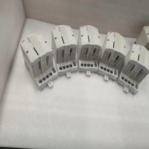
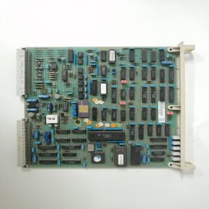
-300x300.jpg)
Reviews
There are no reviews yet.