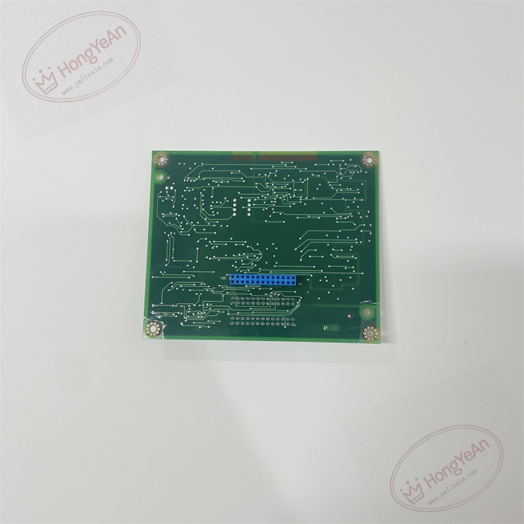
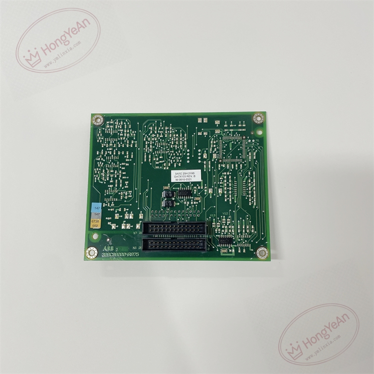
Description
Hardware and Performance Specifications Auxiliary supply: 24 V DC, 18‑30 V DC wide‑range input Power consumption: ≤11 W Input channels: 24‑channel galvanic‑isolated digital input Output channels: 12‑channel transistor digital output Signal level: DI 24 V DC; DO 24 V DC transistor output Isolation voltage: Reinforced galvanic isolation between field‑side and drive internal circuit Communication interfaces: Internal DDCS drive bus Mounting mode: Plug‑in expansion board for DCS500/DCS800 DC drive cabinet Protection class: IP20 Operating temperature: ‑25 ℃ ~ +70 ℃ Storage temperature: ‑40 ℃ ~ +85 ℃ Humidity: 5‑95 %RH non‑condensing EMC compliance: Comply with IEC 61000‑4 series industrial electromagnetic‑compatibility standards Dimension & weight: approx. 365 × 190 × 40 mm, weight approx. 0.74 kg Certifications: CE approval
Main Functions Expand high‑density digital I/O resources for DCS500/DCS800 DC drive. Collect field‑side interlock signal, contactor feedback, limit‑switch, safety‑loop status binary input signals. Output digital control signals for external interlock logic, alarm indication and auxiliary equipment linkage. Realize electrical isolation between field‑side circuit and drive control circuit, prevent field surge interference from damaging main‑control hardware. Front‑panel LED indicators display power‑on status, each channel signal status and hardware‑fault alarm codes for on‑site inspection. Hardware self‑diagnosis detects channel open‑circuit abnormality, internal circuit faults, upload fault‑alarm information to DC drive main controller. Parameter configuration and channel diagnosis are completed by ABB DriveWindow engineering software.
Installation Requirement Plug‑in installation inside DCS500 / DCS800 DC drive cabinet. Strictly separate high‑power power cables and weak‑signal I/O wiring, signal cables adopt shielded twisted‑pair. Ensure reliable cabinet protective grounding. After board replacement, confirm full part‑number DATX133 / 3ASC25H219B matches original project configuration, download complete drive parameter file. Perform point‑to‑point channel‑loop test, verify input‑signal acquisition and output‑action function. Different hardware revisions cannot be directly interchanged without parameter adaptation. Do not put into service until no hardware self‑diagnosis fault alarm exists.
Typical Application Scenarios Digital‑I/O‑expansion‑board spare‑part for ABB DCS500/DCS800 DC drive systems; widely used for heavy‑duty interlock‑signal processing in metallurgy, papermaking and textile DC‑speed‑regulation equipment; used for drive system maintenance and spare‑part replacement.
Key Features
- Enhanced high‑density I/O expansion board, more channels than DATX130/DATX131, suitable for equipment with large‑quantity interlock signals.
- Reinforced galvanic‑isolation design, resist surge and ground‑loop interference under complex industrial‑site environment.
- Per‑channel LED status indication, convenient for field commissioning and fault‑location.
- Plug‑in cabinet‑mount structure, convenient for on‑site replacement and maintenance.
- Strict full‑part‑number matching shall be observed during spare‑part replacement; cannot be directly substituted by DATX130 / DATX131 without parameter re‑configuration.
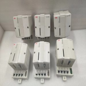
-300x300.jpg)
Reviews
There are no reviews yet.