Description
Hardware & Electrical Specifications
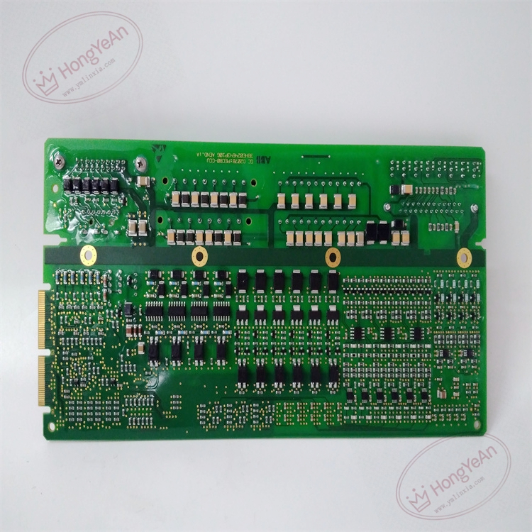
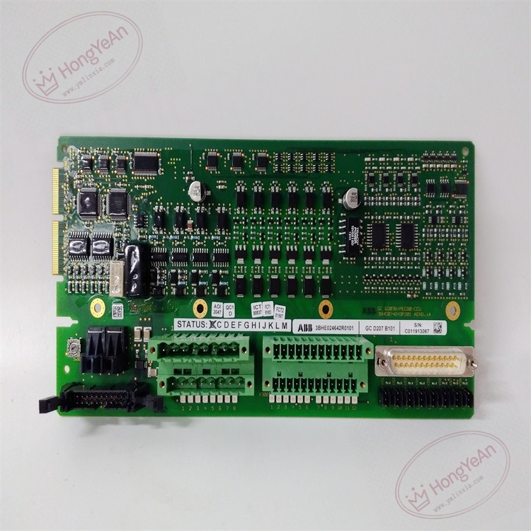
- Model:GCD207B101
- Part Number:3BHE024642R0101
- Module Type:Gate‑Drive Pulse Transformer Board + Mixed I/O Interface Board
- Main Function:Thyristor firing pulse generation, galvanic isolation, field analog/digital signal acquisition
- Pulse Output Channels:6 pulse transformer output channels for 3‑phase thyristor bridge
- Signal Input:Multi‑channel analog measurement input, digital status feedback input
- Logic Power Supply:24 V DC (‑15% ~ +10%) supplied by system back‑plane
- Max power consumption:12 W
- Pulse isolation voltage:≥3000 V AC between control side and power side
- Insulation resistance:>100 MΩ @ 500 V DC
- Dielectric strength:2800 V AC 1 minute between low‑voltage logic and high‑voltage power circuit
- On‑board protection:Surge absorption for pulse outputs, transient over‑voltage clamping for signal inputs
Environmental Specifications
- Operating temperature:0 ℃ ~ +55 ℃
- Storage temperature:‑20 ℃ ~ +70 ℃
- Relative humidity:5%‑95% non‑condensing
- Protection degree:IP20 (installed inside excitation cabinet)
- EMC compliance:IEC 61000‑6‑2 industrial electromagnetic immunity standard
- Certifications:CE
Mechanical Data
- Installation:Plug‑in board installed inside UNITROL excitation cabinet, fixed by screw fasteners
- Connectors:High‑density D‑sub connector, multiple screw terminal blocks for field signals, back‑plane gold‑finger connector
- Suitable wire cross‑section:0.75 mm²‑2.5 mm² copper cable for terminals
- Terminal tightening torque:0.6‑1.0 N·m
- Dimension:180 mm × 142 mm × 38 mm
- Weight:approx 0.60 kg
Main Functions
- Three‑phase thyristor firing pulse generation:Convert phase‑angle control command from main controller into isolated trigger pulses, drive power thyristor rectifier bridge for generator excitation current regulation. Pulse transformers provide high‑voltage galvanic isolation between control unit and power circuit。
- Mixed‑signal acquisition:Collect analog signals such as excitation voltage, excitation current, and digital status feedback from cabinet auxiliary relays and circuit breakers, transmit sampled data back to main controller.
- Real‑time hardware monitoring:Monitor pulse output status, thyristor working state, detect loss‑of‑pulse, thyristor mis‑fire, over‑voltage transient fault.
- On‑board multi‑LED status indication
- Green LED:Power supply normal
- Yellow LED:Pulse output active
- Red LED:Board fault / thyristor firing fault
- Fault diagnosis & fault code upload:Detect pulse channel failure, signal input abnormal, internal circuit fault. Fault information is uploaded to excitation controller, displayed on local HMI and remote DCS system for alarm.
- Signal conditioning circuit:On‑board filter for field measurement signals, suppress high‑frequency interference from power cabinet environment, improve measurement accuracy.
Installation & Wiring Requirements
- Install board inside UNITROL excitation cabinet, tighten fixing screws; ensure gold‑finger back‑plane connector fully engaged.
- Keep sufficient cabinet ventilation; avoid conductive dust, corrosive gas. This board locates near high‑power thyristor components, pay attention to heat dissipation.
- Strictly separate high‑voltage pulse wiring and low‑level measurement signal wiring, run cables in different wiring channels to reduce interference coupling.
- Shielded twisted‑pair cable must be used for analog measurement signals; single‑end shield grounding inside cabinet.
- Cabinet protective grounding must strictly follow excitation system grounding specification, guarantee isolation performance and anti‑interference capability.
- Do not perform hot‑swap operation; power off whole excitation cabinet before plug‑in or removal, prevent high‑voltage damage to board and personal safety hazard.
-300x300.jpg)
-300x300.jpg)
Reviews
There are no reviews yet.