Description
Hardware & Electrical Specifications
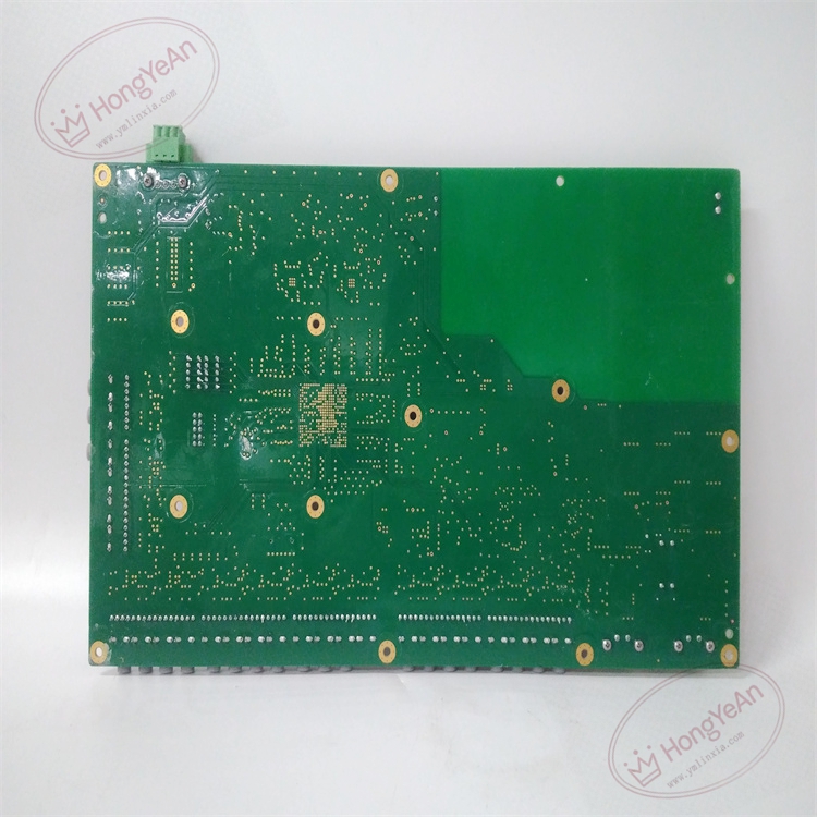
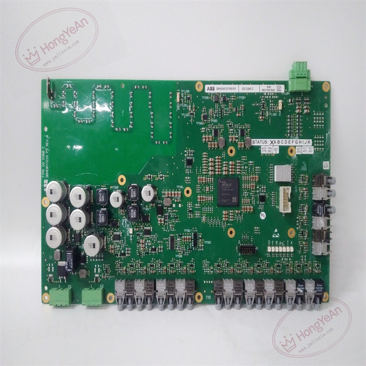
- Model:GDD360C
- Part Number:3BHE047217R0101
- Module Type:IGCT Gate‑Drive Board
- Signal Input:Multi‑channel optical fiber receiving trigger instructions
- Gate drive output:High‑energy turn‑on pulse, negative bias turn‑off, peak pulse current matched for IGCT device
- Fault detection:Vce monitoring, device short‑circuit detection, drive power undervoltage lockout, microsecond‑level soft turn‑off protection
- Logic power supply:24 V DC (‑15% ~ +10%)
- Max power consumption:15 W
- Galvanic isolation rating:≥3000 V AC between control side and power side
- Dielectric strength:3000 V AC 1 min
- Insulation resistance:>100 MΩ @ 500 V DC
- On‑board protection:Transient surge clamping for drive output, EMC filtering for fiber receiving circuit, built‑in filter capacitor group
Environmental Specifications
- Operating temperature:‑10 ℃ ~ +60 ℃
- Storage temperature:‑40 ℃ ~ +85 ℃
- Relative humidity:5%‑95% non‑condensing
- Protection degree:IP20 (installed inside power cabinet)
- EMC compliance:IEC 61000‑6‑2 industrial electromagnetic immunity standard
- Certifications:CE
Mechanical Data
- Installation:Euro‑card plug‑in board, fixed by front panel locking handles, connected via back‑plane gold‑finger connector
- Interfaces:Optical fiber ports, back‑plane gold‑finger connector, screw terminal blocks for auxiliary power and fault signal
- Suitable wire cross‑section:0.75 mm²‑2.5 mm² copper cable
- Terminal tightening torque:0.6‑1.0 N·m
- Dimension:233 mm × 160 mm × 32 mm
- Weight:approx 0.75 kg
Main Functions
- Optical‑fiber signal reception & IGCT gate pulse amplification:Receive optical trigger commands from main control board, convert optical signals into high‑energy gate drive pulses to control IGCT turn‑on and turn‑off. Optical fiber transmission effectively eliminates strong electromagnetic interference inside high‑power cabinet。
- Ultra‑fast hardware protection:Real‑time monitor IGCT Vce saturation voltage, detect short‑circuit, over‑current and drive power undervoltage faults. When fault occurs, implement microsecond‑level soft turn‑off to prevent permanent damage to power semiconductor devices.
- Fault status feedback transmission:Convert detected fault information into optical‑fiber signal and upload to main CPU board. Fault codes can be displayed on local HMI and remote DCS alarm system for maintenance troubleshooting.
- Multi‑LED on‑board status indication
- Green LED:Board auxiliary power supply normal
- Yellow LED:Fiber signal input valid, gate drive output active
- Red LED:IGCT fault / drive circuit abnormal
- High‑voltage galvanic isolation:Isolate low‑voltage control circuit and high‑voltage power circuit, prevent high‑voltage from penetrating into control unit, protect controller hardware and personal safety.
- Negative bias suppression of false turn‑on:Apply stable negative bias voltage during IGCT off‑state, restrain mis‑turn‑on caused by high dv/dt interference in power cabinet environment.
Installation & Wiring Requirements
- Insert board into standard Euro‑card cabinet slot, lock front‑panel handles; ensure back‑plane gold‑finger connector fully contacts. Hot‑swap is strictly forbidden; cut off cabinet total power before plug‑in or removal.
- Ensure good cabinet ventilation; the board is adjacent to high‑power heating components, pay attention to heat dissipation, avoid conductive dust and corrosive gas accumulation.
- Optical fiber laying must avoid sharp bending; minimum bending radius ≥30 mm; separate optical fiber cables from high‑voltage power cables.
- Gate‑drive wiring, fiber signal wiring and main‑circuit high‑power wiring must be routed in separate cable ducts to reduce interference coupling.
- Cabinet protective grounding must strictly follow excitation / medium‑voltage drive system grounding specification to guarantee isolation performance and anti‑interference capability.
- Verify 24 V DC logic power supply is within tolerance range; over‑voltage will cause permanent damage to gate‑drive circuit.
-300x300.jpg)
Reviews
There are no reviews yet.