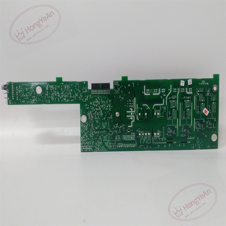
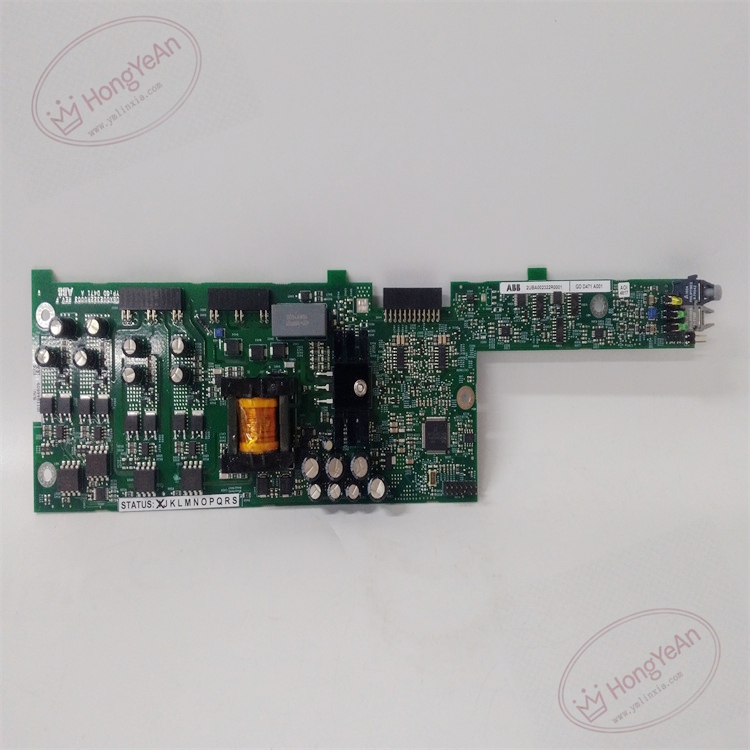
Description
Hardware & Electrical Specifications
- Model:GDD471A001
- Part Number:2UBA002322R0001
- Module Type:Power‑Unit Integrated Control & IGBT Gate‑Drive Board
- Optical Interface:Multi‑channel fiber‑optic transceiver for PWM command and fault feedback
- Power Device:Dual‑channel IGBT gate‑drive output; +15 V turn‑on, ‑8 V negative bias turn‑off; peak drive current ≥2.5 A per channel
- Signal Acquisition:DC‑link voltage, cell output current, power‑cell temperature sampling circuit on‑board
- Local logic power supply:24 V DC (‑15% ~ +10%)
- Max power consumption:13 W
- Galvanic isolation:≥2500 V AC between fiber logic side and high‑voltage power‑cell side
- Dielectric strength:2500 V AC 1 minute
- Insulation resistance:>100 MΩ @ 500 V DC
- On‑board protection:IGBT short‑circuit protection, Vce desaturation detection, drive power undervoltage lockout, over‑temperature protection, surge clamping for sampling circuit
- Local auxiliary power generation:On‑board isolated auxiliary power supply for gate‑drive circuit inside power cell
Environmental Specifications
- Operating temperature:‑10 ℃ ~ +60 ℃
- Storage temperature:‑40 ℃ ~ +85 ℃
- Relative humidity:5%‑95% non‑condensing
- Protection degree:IP20 (installed inside MV drive power‑cell cabinet)
- EMC compliance:IEC 61000‑6‑2 industrial electromagnetic immunity standard
- Certifications:CE
Mechanical Data
- Installation:Fixed inside ACS580MV power‑cell unit by screw fasteners; connect via high‑density internal connectors
- Interfaces:Optical fiber ports, high‑current gate‑drive terminals, sampling signal terminals, 24 V DC power terminals
- Suitable wire cross‑section:0.75 mm²‑2.5 mm² copper cable for signal terminals
- Terminal tightening torque:0.6‑1.0 N·m
- Dimension:225 mm ×115 mm ×35 mm
- Weight:approx 0.68 kg
Main Functions
- Optical‑fiber command reception & IGBT gate‑drive output:Receive PWM switching instructions transmitted by optical fiber from main controller, convert optical signals into high‑current gate drive signals to control IGBT turn‑on / turn‑off. Optical fiber transmission eliminates heavy electromagnetic interference inside high‑voltage power cell cabinet.
- Power‑cell local real‑time sampling:Sample DC‑link voltage, cell output current and power‑cell internal temperature, send sampled data back to main controller via optical fiber for drive closed‑loop control.
- Ultra‑fast hardware fault protection:Detect IGBT short‑circuit, desaturation, drive power undervoltage, power‑cell over‑temperature fault. When fault occurs, execute microsecond‑level IGBT soft‑turn‑off, trigger power‑cell bypass logic, realize fault‑tolerant operation, prevent single‑cell fault leading to full drive shutdown.
- Fault status feedback:Encode fault type, fault channel and temperature information into optical‑fiber messages and upload to main controller; fault alarm can be displayed on drive HMI and remote DCS system.
- Multi‑LED on‑board status indication
- Green LED:Board auxiliary power supply normal, fiber link ok
- Yellow LED:PWM drive output active
- Red LED:Power‑cell fault / gate‑drive circuit abnormal
- Independent power‑cell bypass control:On‑board hardware logic implements power‑cell bypass without relying on main controller, improve medium‑voltage drive system availability.
- Negative bias suppression of false turn‑on:Output stable negative bias voltage during IGBT off‑state, restrain misleading‑turn‑on caused by high dv/dt interference inside power cell.
Installation & Wiring Requirements
- Install board inside ACS580MV power‑cell compartment, tighten fixing screws; ensure all internal connectors fully engaged. Hot‑swap is strictly forbidden; cut off high‑voltage and control power supply of power‑cell before disassembly and assembly.
- Guarantee power‑cell cabinet ventilation and heat dissipation; avoid conductive dust accumulation on PCB surface.
- Optical fiber laying must avoid sharp bending; minimum bending radius ≥30 mm; keep fiber cables away from high‑power copper busbars.
- Gate‑drive wiring, sampling signal wiring and high‑voltage main‑circuit busbar must be physically separated to reduce interference coupling.
- Power‑cell cabinet protective grounding must strictly follow ABB medium‑voltage drive grounding specification to guarantee isolation performance and anti‑interference capability.
- Verify 24 V DC logic power supply within allowable tolerance; over‑voltage will cause permanent damage to gate‑drive circuit.
-300x300.jpg)
-300x300.jpg)
Reviews
There are no reviews yet.