

Description
Hardware & Electrical Specifications
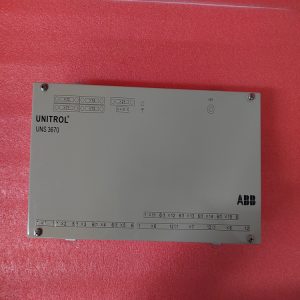
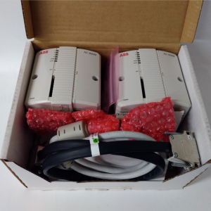
- Model:PFEA111‑20
- Part Number:3BSE050090R20
- Module Type:Tension Electronics Amplifier
- Mounting:DIN‑rail mounting, IP20 protection grade
- Power supply:24 V DC (18‑36 V DC), power consumption 7.5 WABB Group
- Sensor channel:2‑channel load‑cell input; 330 Hz sensor excitation 0.5 A rmsABB Group
- Analog output:0‑10 V, 4‑20 mA configurable
- Communication:Profibus‑DP fieldbus interface
- Display:2×16 character multi‑language LCD with setting keysABB Group
- Measuring accuracy:±0.1% full scale
- Galvanic isolation:between sensor side and control logic side
- On‑board protection:overload protection, signal filtering, short‑circuit protection
- Compatibility note:Cannot run standalone; match ABB PFCL / PFTL tension sensors, must match host system configuration.
Environmental Specifications
- Operating temperature:‑10 ℃ ~ +55 ℃ABB Group
- Storage temperature:‑40 ℃ ~ +70 ℃
- Relative humidity:5%‑95% non‑condensing
- Installation location:Inside industrial control cabinet
- EMC compliance:IEC 61000‑6‑2
- Certifications:CE, UL61010C
Mechanical Data
- Weight:approx 0.30 kg
- Dimension:125 mm × 100 mm × 45 mm
- Terminals:screw terminal blocks for sensor, power, analog signal and Profibus‑DP bus
- Recommended wire cross‑section:0.75 mm²‑2.5 mm² copper cable for signal terminals
- Terminal tightening torque:0.6‑1.0 N·m
Main Functions
- Supply excitation and acquire measuring signal from dual tension load‑cells.
- Calculate tension value of individual channel, sum(A+B) and difference(A‑B).
- Configurable digital filtering for suppressing mechanical vibration and noise interference.
- Analog output 4‑20 mA / 0‑10 V for PLC / drive closed‑loop tension control.
- Local LCD display for tension value reading, parameter setting and status diagnosis.
- Profibus‑DP communication for remote reading of tension value, alarm and parameter configuration.
- Channel self‑diagnosis: detect sensor break, overload and circuit fault, report alarm status.
- LED status indication:
- Green LED:Power supply normal, unit healthy
- Yellow LED:Measuring signal / Profibus‑DP communication active
- Red LED:Over‑load / sensor fault / unit hardware fault
Installation & Wiring Requirements
- Cut off power supply before wiring or replacement. Mount PFEA111‑20 firmly on DIN‑rail inside cabinet. Hot‑swap is forbidden.
- Connect load‑cell sensor cable, power cable, analog output and Profibus‑DP bus cable strictly per wiring drawing; separate sensor weak‑signal cables from high‑power cables to reduce electromagnetic interference.
- Complete grounding according to ABB tension‑system specification.
- After replacement, perform load‑cell calibration, set filter parameters and Profibus‑DP station address; verify measuring output and bus communication function before commissioning.
- Replacement note: parameter download and recalibration are required after unit replacement. Cannot directly swap with RS485 Modbus version 3BSE028140R0020, communication interface hardware differs.
-300x300.jpg)
Reviews
There are no reviews yet.