Description

Technical background & performance features
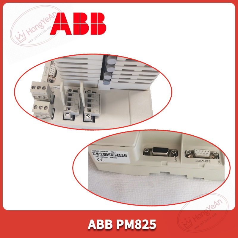
Rack plug‑in structure, part number PM825.
Equipped with onboard processing chip and memory resources for control program execution.
Supports ModuleBus communication to connect S800 remote I/O stations.
System configuration, user logic and fault logs are stored in internal memory area.
Working power is supplied by control rack backplane circuit.
Front‑panel LED lamps display operating mode, runtime status and hardware fault information.
Non‑condensing cabinet‑internal installation is required. Spare parts should avoid mechanical impact and static‑electric damage.
Cannot work independently. Needs matching control rack, base unit and consistent system firmware. Hot‑swap under powered condition is not permitted.
Typical application scenarios
Widely adopted in power‑plant auxiliary control cabinets, chemical‑process monitoring and water‑treatment automation projects built on 800xA platform.
It undertakes core logic operation, interlock judgment and closed‑loop regulation tasks, realizing data docking between field equipment and central monitoring system.
On‑site installation points to note
Power off the whole control rack before installing or removing this controller.
Take anti‑static precautions when handling circuit‑board hardware.
Insert into designated slot and lock firmly to guarantee stable backplane pin contact.
Complete visual inspection for PCB scratches and component damage before power‑on.
Back‑up the full project from original hardware before replacement. Download project and matched firmware to new PM825 unit.
After power‑on, verify controller running status, communication with remote I/O and HMI connection.
Maintain good cabinet ventilation; continuous high temperature will accelerate ageing of chip and memory components.
Common on‑site phenomena and analysis ideas
All LED indicators keep off: Check rack backplane power supply, investigate slot pin contamination or internal power‑circuit damage on module.
Controller cannot switch to run status: Check project integrity, firmware compatibility and hardware configuration parameters.
Occasional spontaneous reset: Troubleshoot power supply stability, backplane contact condition or cabinet over‑temperature.
Partial remote I/O station communication dropout: Confirm bus cable layout, terminal resistance setting and project download completeness.
After surge fault occurs on site: Replace PM825 module, and inspect adjacent communication and I/O boards for secondary damage.
-300x300.jpg)
Reviews
There are no reviews yet.