Description
Technical background & performance features
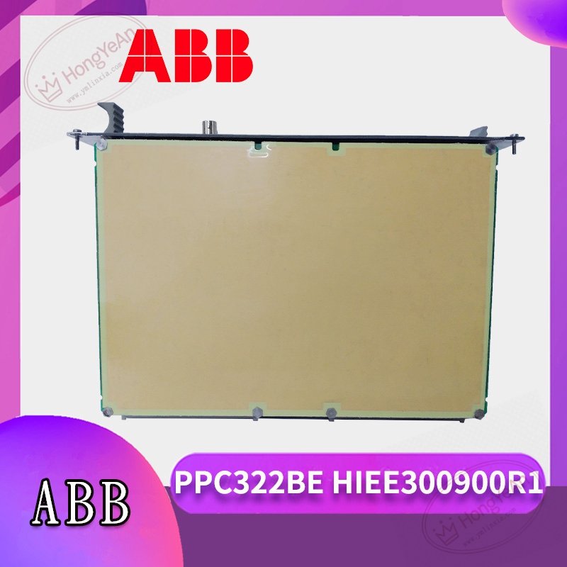
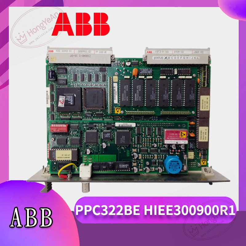
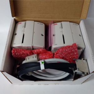
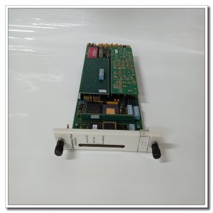
Rack‑mount plug‑in processor board, part number PPC322BE‑HIEE300900R1.
On‑board CPU completes closed‑loop excitation regulation logic, records operation events and fault alarm information.
Realizes signal interaction with sampling boards and pulse trigger boards through internal rack bus.
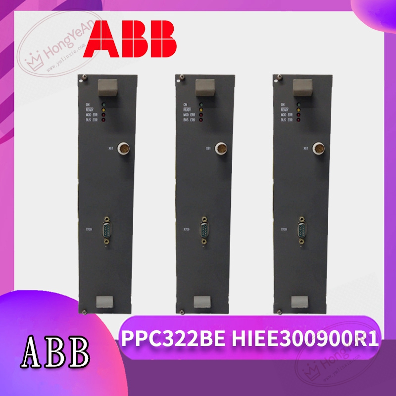
Front‑panel LED indicators reflect board running state, regulation status and fault codes.
Operating power is supplied by excitation cabinet back‑plane power circuit.
Must work in non‑condensing cabinet environment. Spare parts need dry storage, prevent mechanical shock and static‑electric damage.
Independent operation is unavailable. Matching excitation rack, signal acquisition hardware and consistent firmware version are required. Hot‑swap under energized state is forbidden.
Typical application scenarios
Mainly applied in large‑scale generator excitation control cabinets of power plants.
As core control unit of excitation system, it stabilizes generator terminal voltage and realizes reactive‑power adjustment during unit operation.
On‑site installation points to note
Cut off cabinet AC and DC power supply before installing or removing this board.
Follow anti‑static operation requirements when handling circuit‑board hardware.
Insert into specified slot and lock tightly to guarantee reliable backplane contact.
Keep weak‑signal wiring separated from high‑power main‑loop cables to reduce electromagnetic interference.
Visually inspect PCB for scratches and component damage before power‑on.
Backup original excitation parameters before replacement, download matching firmware and parameter configuration to new board.
After power‑on, carry out static debugging and no‑load excitation test, verify voltage regulation performance.
Ensure cabinet cooling works normally; long‑term high temperature will accelerate ageing of onboard chips.
Common on‑site phenomena and analysis ideas
All LEDs remain off: Check cabinet back‑plane power supply loop, slot pin contamination or internal power‑circuit damage of the board.
Excitation cannot build‑up: Inspect sampling signal loop, firmware matching status and parameter configuration rationality.
Voltage out‑of‑control or unstable regulation: Focus on signal sampling accuracy, board hardware fault or parameter setting deviation.
System reports processor communication fault: Check backplane contact condition and inter‑board cable connection.
After on‑site short‑circuit surge fault: Replace PPC322BE‑HIEE300900R1 board, meanwhile check adjacent sampling and trigger boards for secondary damage.
-300x300.jpg)
Reviews
There are no reviews yet.