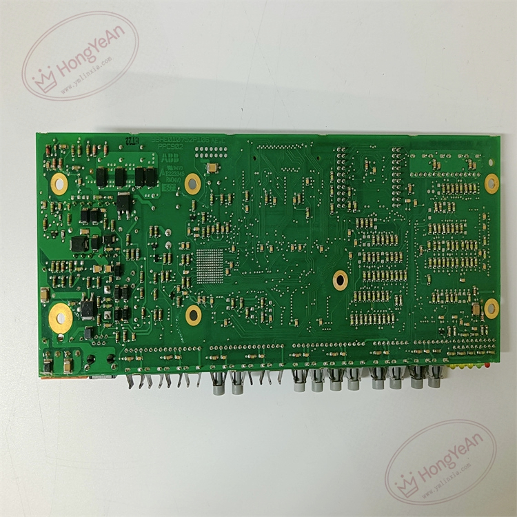
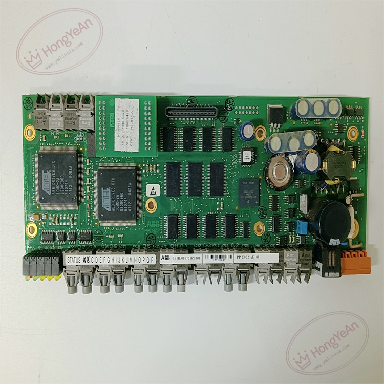
Description
Hardware & Electrical Specifications
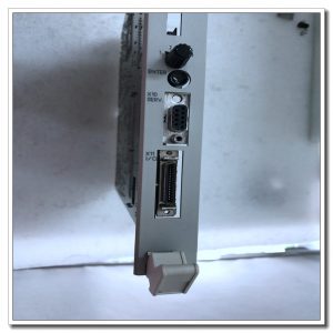
- Model:PPC902AE101
- Part Number:3BHE010751R0101
- Module Type:High‑Performance Power Electronic Processor Board
- On‑board Processor:High‑speed 32‑bit RISC real‑time processor for power‑electronic control
- Memory:Flash for firmware & project parameters; SDRAM for real‑time data, fault waveform snapshot storage
- Communication:High‑speed parallel back‑plane bus; multi‑channel fiber‑optic transceivers for high‑speed inter‑board data exchange
- Logic power supply:24 V DC (‑15% ~ +10%)
- Max power consumption:14.5 W
- Galvanic isolation:≥2500 V AC between field side and internal logic circuit
- Dielectric strength:2500 V AC 1 minute
- Insulation resistance:>100 MΩ @ 500 V DC
- On‑board protection:Reverse‑polarity protection for 24 V power input, EMC filter network, hardware watchdog circuit, conformal coated PCB
Environmental Specifications
- Operating temperature:‑10 ℃ ~ +60 ℃
- Storage temperature:‑40 ℃ ~ +85 ℃
- Relative humidity:5%‑95% non‑condensing
- Protection degree:IP20 (installed inside excitation / MV drive cabinet)
- EMC compliance:IEC 61000‑6‑2 industrial electromagnetic immunity standard
- Certifications:CE
Mechanical Data
- Installation:Euro‑card plug‑in board, fixed by front‑panel locking handles, connected via back‑plane gold‑finger connector
- Interfaces:Back‑plane gold‑finger connector, LC fiber‑optic interfaces, debug service port
- Suitable wire cross‑section:0.75 mm²‑2.5 mm² copper cable for signal terminals
- Terminal tightening torque:0.6‑1.0 N·m
- Dimension:233 mm × 160 mm × 30 mm
- Weight:approx 0.78 kg
Main Functions
- High‑speed real‑time control algorithm execution:Run high‑precision AVR automatic voltage‑regulation, excitation‑limiter, reactive‑power / power‑factor closed‑loop control algorithm for synchronous‑generator excitation system; complete converter modulation algorithm for medium‑voltage drive.
- Precision firing pulse sequence generation:Output synchronized pulse timing commands to pulse distribution driver board, realize high‑precision phase‑angle control for thyristor / IGCT rectifier bridge.
- System‑level data interaction and coordination:Exchange high‑speed sampling data, control commands and fault information with measurement board, pulse driver board and communication board via back‑plane bus and fiber‑optic links.
- Parameter storage and disturbance recording:Store project configuration parameters locally; capture fault snapshot, event log and disturbance‑recording waveforms for post‑fault analysis.
- Hardware watchdog safety monitoring:Built‑in hardware watchdog; automatically block pulse output when processor runs abnormally, prevent uncontrolled power‑electronic output.
- Comprehensive self‑diagnosis function:Detect firmware exception, memory fault, back‑plane bus and fiber‑link communication error. Fault codes are uploaded to local HMI and remote DCS alarm system.
- On‑board multi‑LED status indication
- Green LED:Board 24 V auxiliary power supply normal, processor running healthy
- Yellow LED:Back‑plane bus / fiber‑optic data transmitting / receiving active
- Red LED:Processor fault / communication link failure / board hardware error
Installation & Wiring Requirements
- Insert board into standard Euro‑card cabinet slot, lock front‑panel handles; ensure back‑plane gold‑finger connector fully engaged. Hot‑swap is strictly forbidden; cut off cabinet total power before disassembly and assembly.
- Ensure cabinet ventilation and heat dissipation; avoid conductive dust and corrosive gas accumulating on PCB surface.
- Optical fiber laying must avoid sharp bending; minimum bending radius ≥30 mm; keep fiber cables away from high‑power copper busbar to reduce interference coupling.
- Cabinet protective grounding must strictly follow ABB AC800‑PEC / UNITROL6000 system grounding specification to guarantee anti‑interference capability.
- Verify 24 V DC logic power supply within allowable tolerance; over‑voltage will cause permanent hardware damage.
- After replacement, verify firmware compatibility with all peripheral boards; download matched firmware and project parameters; perform closed‑loop control commissioning test.
Reviews
There are no reviews yet.