Description
Technical background & performance features
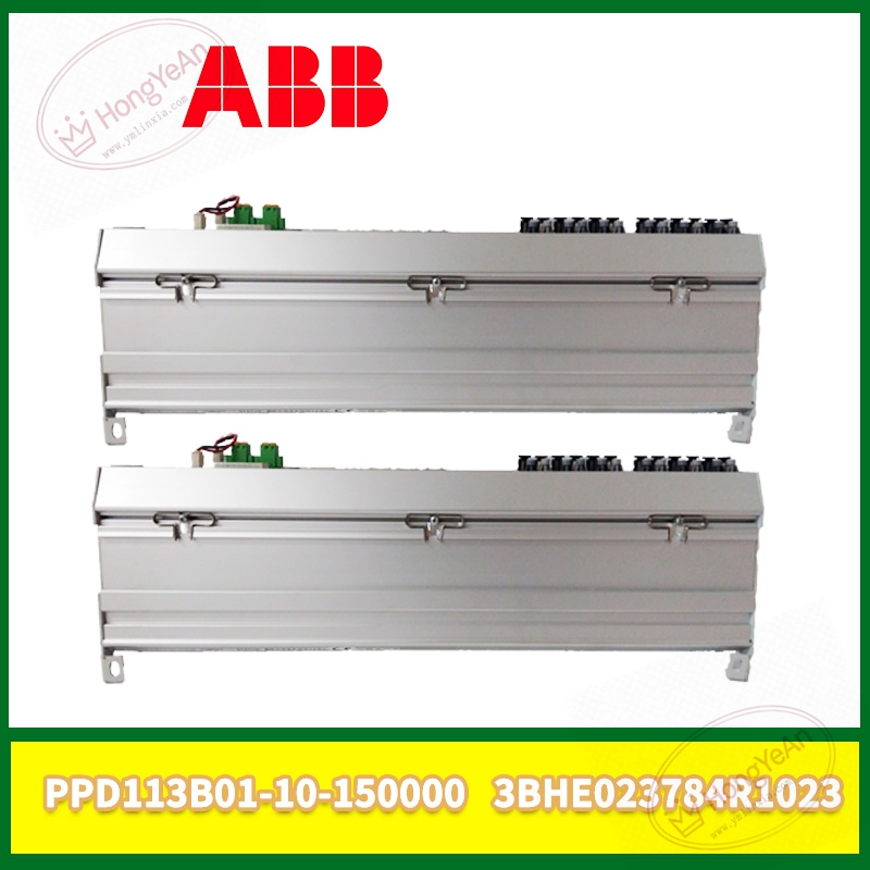
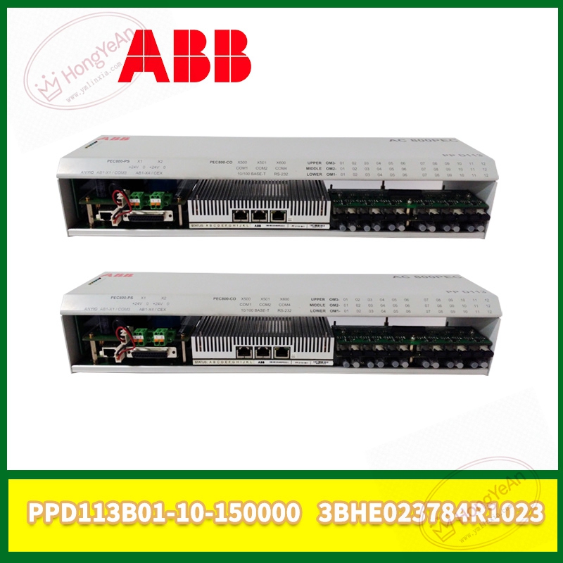
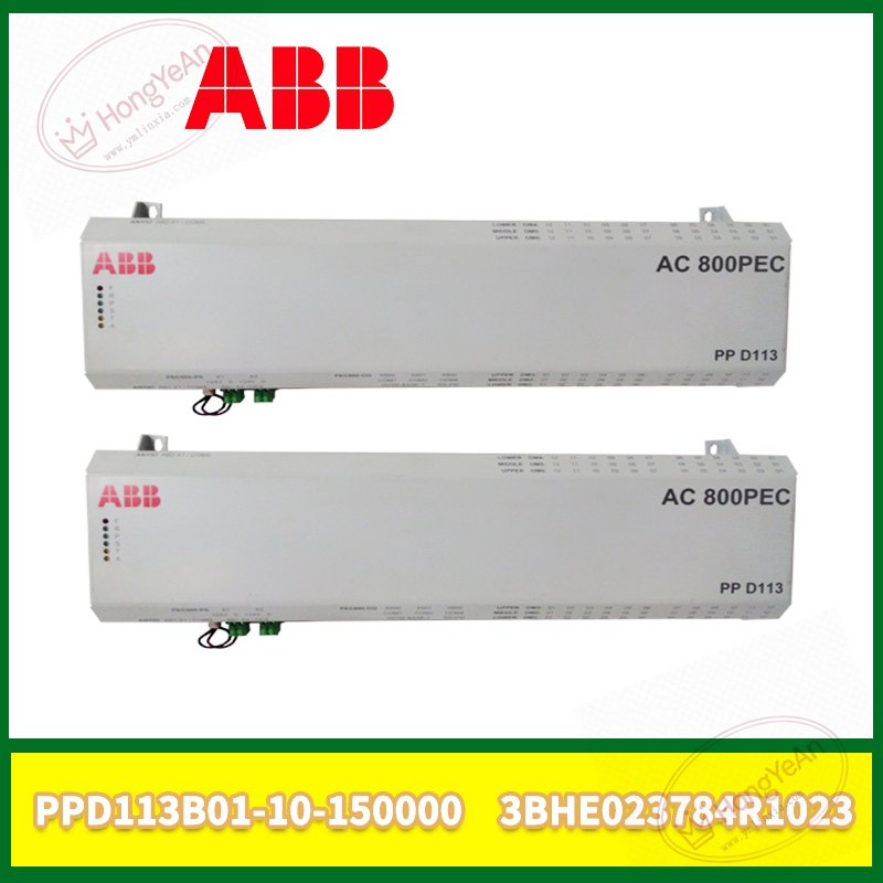
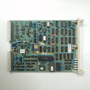
Rack‑mount plug‑in trigger control board, full part number PPD113B01‑10‑150000‑3BHE023784R1023.
Responsible for receiving optical fiber commands, processing pulse logic and outputting trigger signals to thyristor power units.
On‑board circuit realizes signal isolation, pulse amplification and fault signal feedback.
Front‑panel LED lamps show working status, pulse output state and hardware fault alarms.
Power supply is provided by converter cabinet internal auxiliary power circuit.
Installed inside non‑condensing power cabinet. Spare parts should avoid mechanical impact and static electricity damage.
Can not run independently. Must cooperate with main control board, optical fiber link and thyristor power assembly. Firmware version needs to match whole‑set equipment. Hot‑swap under power is strictly prohibited.
Typical application scenarios
Mostly deployed in generator excitation cabinets and large‑capacity industrial rectifier converter devices.
It delivers accurate trigger pulses to thyristor modules, ensuring stable rectification and excitation output performance.
On‑site installation points to note
Cut off all high‑voltage and auxiliary power supply of converter cabinet before disassembly or installation.
Strictly implement anti‑static measures when contacting circuit board.
Insert into designated slot and lock firmly to keep reliable backplane contact.
Check optical fiber connectors for dirt or damage, arrange optical fiber cables away from high‑voltage power loops.
Visually check PCB surface for burn marks, scratches and component damage before power‑on.
Confirm firmware consistency after board replacement. Complete static pulse test before putting into actual operation.
Keep cabinet cooling fan in good condition. Continuous high temperature will shorten service life of trigger circuit.
Common on‑site phenomena and analysis ideas
All indicator lights do not light up: Check cabinet auxiliary power supply, slot contact status or internal power circuit damage of board.
No pulse output after startup: Inspect optical fiber link, upper‑level controller instruction output and board hardware channel.
Converter cannot build‑up voltage: Check trigger pulse phase sequence, optical fiber signal integrity and thyristor health status.
Intermittent converter block alarm: Caused by poor optical fiber connection, cabinet over‑temperature or aging of onboard components.
After high‑voltage surge fault: Replace PPD113B01‑10‑150000‑3BHE023784R1023 board, and check adjacent main control boards and power units for secondary damage.
-300x300.jpg)
Reviews
There are no reviews yet.