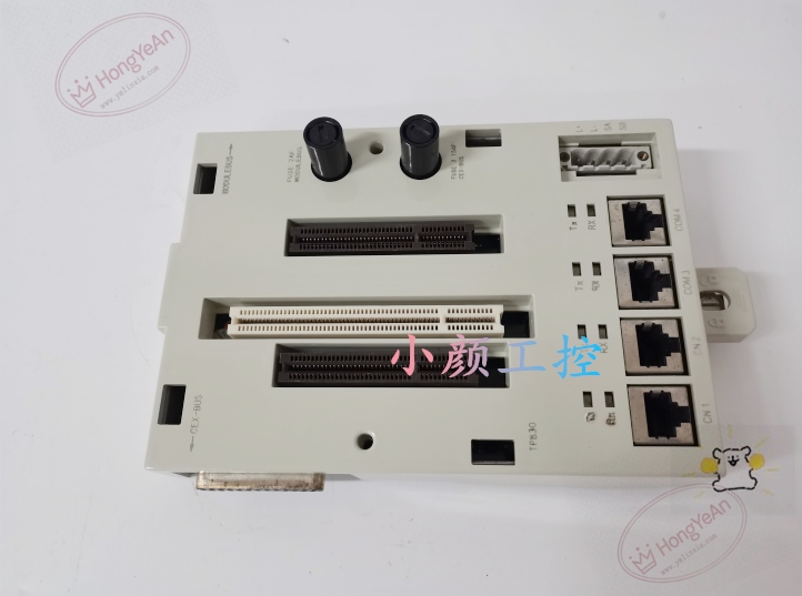
Description
Hardware & Electrical Specifications
‑ Manufacturer: ABB ‑ Compatible System: System 800xA, AC 800M controller series (PM851, PM866, PM867 etc.) ‑ Functional Type: Controller Baseplate Unit ‑ Slots: Processor module slot, dual expansion slots for communication modules ‑ Interfaces: 4 × RJ45 Ethernet ports, 2 × RS‑232 COM ports (COM3, COM4) ‑ Power Supply: 24 VDC ±10 % external power input ‑ Backplane Bus: Proprietary high‑speed internal bus for controller module interconnection ‑ Indicators: Multi‑LED status indicators for power, bus and communication diagnostic ‑ Connectors: Screw terminal block for 24VDC power input, backplane card edge connectors ‑ Mounting: Standard 35 mm DIN‑rail installation with lock‑in mechanism ‑ PCB Finish: Industrial‑grade conformal coating for harsh plant environment
Environmental Specifications
‑ Operating Temperature: ‑25 °C ~ +70 °C ‑ Storage Temperature: ‑40 °C ~ +85 °C ‑ Relative Humidity: 5 %‑95 % non‑condensing ‑ Vibration & Shock: Complies with industrial power‑plant cabinet EMI and transient requirements
Mechanical Data
‑ Weight: approx 0.24 kgDCS Center ‑ Width: 115 mmDCS Center
Core Functions
- Mechanical carrier: Provides slot‑based physical mounting platform for AC 800M CPU and communication expansion cards.
- Internal backplane interconnection: Realizes high‑speed data exchange between processor module and plug‑in communication modules.
- External communication gateway: Offers native Ethernet and RS‑232 serial interfaces for engineering download, HMI connection and serial peripheral devices.
- Central power distribution: Distributes 24 VDC input power to CPU and expansion modules via internal backplane.
- System‑level diagnostics: LED indicators show power status, backplane bus health and communication channel fault information for maintenance troubleshooting.
Installation, Replacement & Critical Warnings
- Cut off 24 VDC power supply before baseplate replacement; TP830 baseplate is non‑hot‑swappable.
- Verify processor and communication module part numbers are compatible with TP830 baseplate; incompatible modules will prevent controller boot‑up.
- Torque 24 VDC power‑input screw terminals properly; loose terminals cause intermittent controller resets.
- After assembly and power‑on, check LED status; complete controller download and communication verification via Control Builder M engineering tool.
-
Common failure mode: Backplane connector pin damage, surge damage to onboard Ethernet/serial transceiver circuits. Inspect power quality when controller fails to boot or random communication drop‑outs occur.
-300x300.jpg)
Reviews
There are no reviews yet.