


Description
Hardware & Electrical Specifications
- Model:UAC389AE02
- Part Number:HIEE300888R0002
- Module Type:Enhanced Measurement Unit Board
- Bus Interface:6U VME back‑plane bus
- Analog Input:Multi‑channel galvanic‑isolated analog inputs for generator voltage and current
- Binary Input:Multi‑channel isolated binary dry‑contact inputs for interlock & auxiliary status
- On‑board resource:Signal conditioning circuit, high‑resolution ADC, hardware fault monitoring logic
- Power supply:24 V DC cabinet internal power
- Max power consumption:14 W
- Galvanic isolation:≥2500 V AC between field‑signal side and VME logic side
- Dielectric strength:2500 V AC 1 minute
- Insulation resistance:>100 MΩ @ 500 V DC
- On‑board protection:Channel surge suppression, ESD protection, over‑range monitoring, conformal coated PCB
- Compatibility note:Must match UNITROL6000 full‑system firmware; backward replacement for UAC383AE01 requires firmware validation; cannot operate standalone.
Environmental Specifications
- Operating temperature:‑10 ℃ ~ +60 ℃
- Storage temperature:‑40 ℃ ~ +85 ℃
- Relative humidity:5%‑95% non‑condensing
- Protection degree:Mounted in excitation cabinet VME rack
- EMC compliance:IEC 61000‑6‑2 industrial electromagnetic immunity standard
- Certifications:CE
Mechanical Data
- Installation:Standard 6U VME Euro‑card, insert into VME rack slot
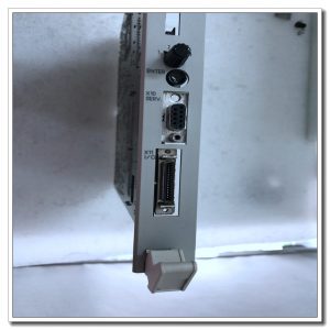
- Interfaces:VME back‑plane gold‑finger connector; terminal blocks for analog & binary field wiring
- Suitable wire cross‑section:0.75 mm²‑2.5 mm² copper cable for signal terminals
- Terminal tightening torque:0.6‑1.0 N·m
- Dimension:6U VME standard board
- Weight:approx 0.76 kg
Main Functions
- Multi‑channel analog signal acquisition and conditioning: Collects generator PT/CT voltage‑current signals, implements filtering, isolation and signal conditioning before A/D conversion.
- High‑resolution A/D conversion: Converts conditioned analog signals to digital values, delivers measurement data to main CPU for AVR closed‑loop regulation, limitation and protection calculation.
- Binary interlock signal processing: Acquires cabinet auxiliary dry‑contact status, converts field signals to digital logic for excitation interlock and sequence control.
- Real‑time data transmission: Uploads analog measured values and binary status to main processor through VME back‑plane bus.
- Channel fault detection: Detects analog signal loss, over‑range, channel abnormality and binary‑input failure, reports detailed fault codes.
- Board‑level self‑diagnosis: Monitors on‑board power, ADC unit and hardware logic status, uploads hardware fault alarms to UNITROL6000 system.
- On‑board multi‑LED status indication
- Green LED:Board power supply normal, board logic running healthy
- Yellow LED:Signal acquisition active, VME data transmission ongoing
- Red LED:Input‑channel fault / board hardware fault alarm
Installation & Wiring Requirements
- Cut off cabinet total power before disassembly and assembly. Insert UAC389AE02 into designated VME slot and lock front‑panel handles firmly. Hot‑swap is strictly forbidden.
- Connect generator measurement cables and binary‑signal cables to corresponding terminal blocks; follow excitation cabinet wiring specification; separate high‑power cables and weak‑signal cables to reduce electromagnetic interference.
- Cabinet protective grounding shall comply with ABB AC800‑PEC / UNITROL6000 system grounding specification.
- After replacement, verify full‑system firmware compatibility with main processor board; download matching project parameters; perform analog‑channel calibration and binary‑input function test before commissioning.
- Replacement note: When replacing older UAC383AE01, confirm system firmware supports UAC389AE02; cannot run independently, must cooperate with PPC‑series main‑processor hardware.
Reviews
There are no reviews yet.