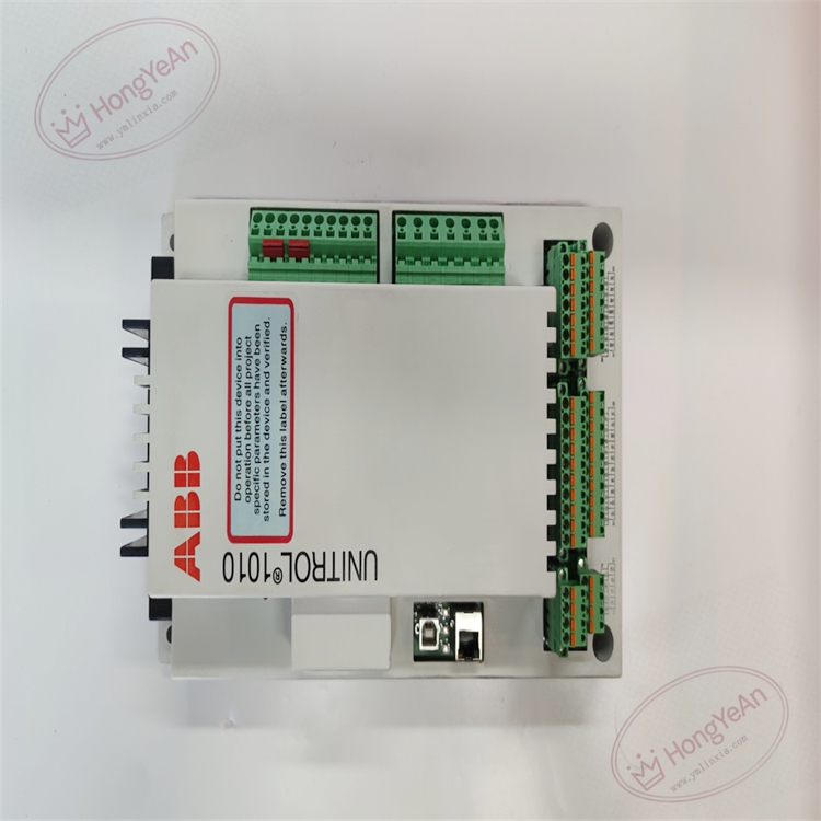
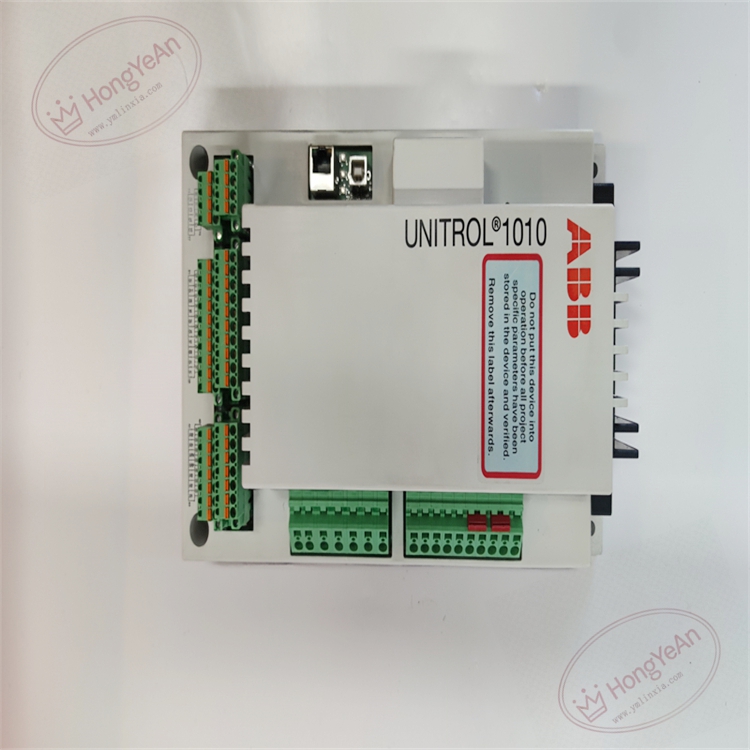
Description
Hardware and Performance Specifications Auxiliary supply: 24 V DC, 9‑36 V DC wide‑range input; AC auxiliary supply is also available Excitation output: Continuous 10 A DC at 55 ℃, short‑time overload 20 A DC for 10 seconds Voltage regulation accuracy: Steady‑state voltage regulation accuracy ≤±0.2%Un Dynamic response: 3‑phase measurement response <20 ms, single‑phase measurement <50 ms Binary I/O: Galvanic‑isolated digital inputs, relay outputs for breaker status acquisition, alarm and protection trip output Communication interfaces: Ethernet, USB; support Modbus‑TCP, Modbus‑RTU. USB supports parameter reading‑writing and debugging without external power supply Mounting mode: Cabinet wall‑mount / rack‑mount integrated unit Operating temperature: ‑25 ℃ ~ +70 ℃ Storage temperature: ‑40 ℃ ~ +85 ℃ Humidity: 5‑95 %RH non‑condensing EMC compliance: Comply with IEC 61000‑4 series industrial EMC standards Dimension & weight: 225 × 165 × 80 mm, weight approx. 2.5 kg Certifications: CE, DNV‑GL marine certification
Main Functions Real‑time acquisition of generator voltage and current measuring signals, execute AVR automatic‑voltage closed‑loop regulation calculation. Multi‑control‑mode switching: auto‑voltage mode, manual field‑current mode, constant reactive‑power control, constant power‑factor control. Built‑in full‑set excitation limit functions: over‑excitation limit, under‑excitation limit, V/Hz limitation, field‑current over‑current protection. Embedded IGBT power circuit, directly output excitation current to generator exciter. Collect field binary signals: breaker auxiliary contacts, external interlock signals; output relay contacts for alarm and protection block. Event logging and disturbance recording, store fault waveforms and operation events with time‑stamp for post‑fault analysis. Multiple communication interfaces realize data exchange with DCS and upper monitoring system. Hardware self‑diagnosis detects faults of measuring loops and internal power units, upload fault codes to upper system. Support parameter configuration, logic debugging and firmware upgrade.
Installation Requirement Wall‑mount or rack‑mount installation inside excitation cabinet. High‑power cables and weak‑signal measuring cables shall be routed separately. Ensure reliable cabinet grounding. Auxiliary 24 V DC power supply shall be kept within rated working range. After unit replacement, confirm hardware version matches original project configuration, download complete excitation project configuration file. Perform voltage‑loop calibration, excitation‑output test, binary‑I/O point‑to‑point test and communication debugging. Different hardware and software versions cannot be directly interchanged without software adaptation. Do not put into service until no hardware self‑diagnosis fault alarm exists.
Typical Application Scenarios Compact digital excitation regulator for small‑and‑medium‑sized synchronous generators in hydropower stations, industrial captive power plants, diesel gensets and marine power systems, applied for excitation‑system maintenance and spare‑part replacement.
Key Features
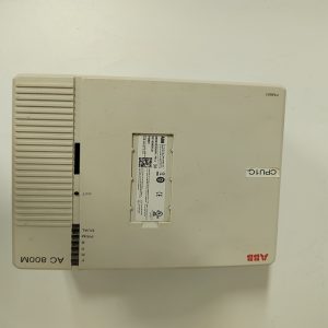
- UNITROL1000‑series integrated compact excitation AVR, all‑in‑one whole‑machine design, no extra main‑board required, convenient for small‑unit retrofitting.
- Multiple optional control modes, embedded full‑set excitation‑limit and protection algorithms to guarantee safe generator operation.
- Fast dynamic response and high‑precision voltage‑regulation performance.
- Multiple standard communication interfaces, easy to connect with plant DCS monitoring system.
- Integrated cabinet‑mount mechanical structure, convenient for on‑site replacement and maintenance; hardware‑version matching must be strictly observed during spare‑part replacement.
- Widely‑used maintenance spare part for ABB small‑and‑medium‑unit excitation systems.
-300x300.jpg)
Reviews
There are no reviews yet.