Description
Hardware Specifications
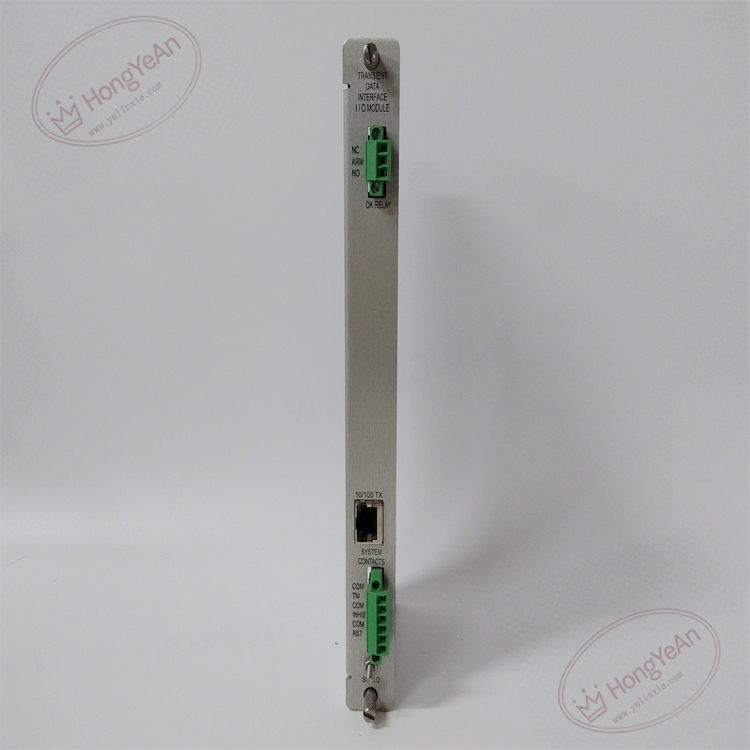
- Part Type: Copper‑ethernet rear I/O small card for TDI communication, dedicated pairing for 3500‑22M front‑end transient data interface module, standalone operation invalid
- Mounting: Rear slot‑1 position of 3500‑05 rack, front‑rear paired‑slot architecture, directly mounted behind 3500‑22M front‑end TDI module adjacent to power supply
- Termination: On‑board RJ45 ethernet port and rack‑OK dry‑contact relay terminals; no field sensor input terminals
- Relay Performance: Rack‑OK dry‑contact relay, used for general rack‑fault annunciation, not permitted for machinery trip interlock circuit
- PCB: Conformal‑coated multi‑layer FR‑4 PCB, delivers anti‑corrosion protection for long‑term continuous operation under oily, dusty industrial cabinet environment
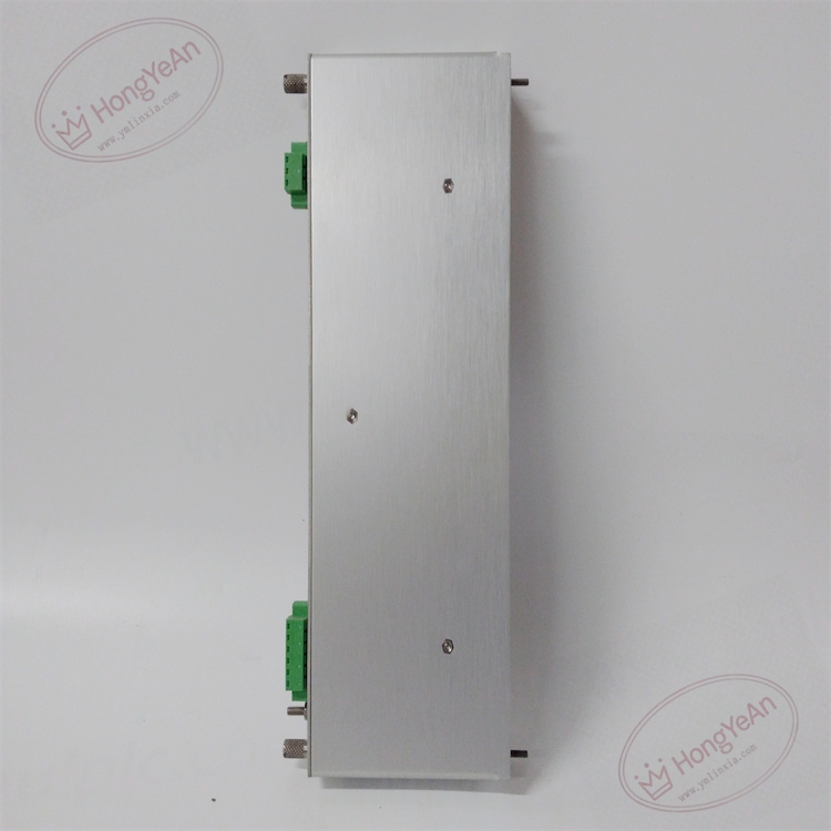
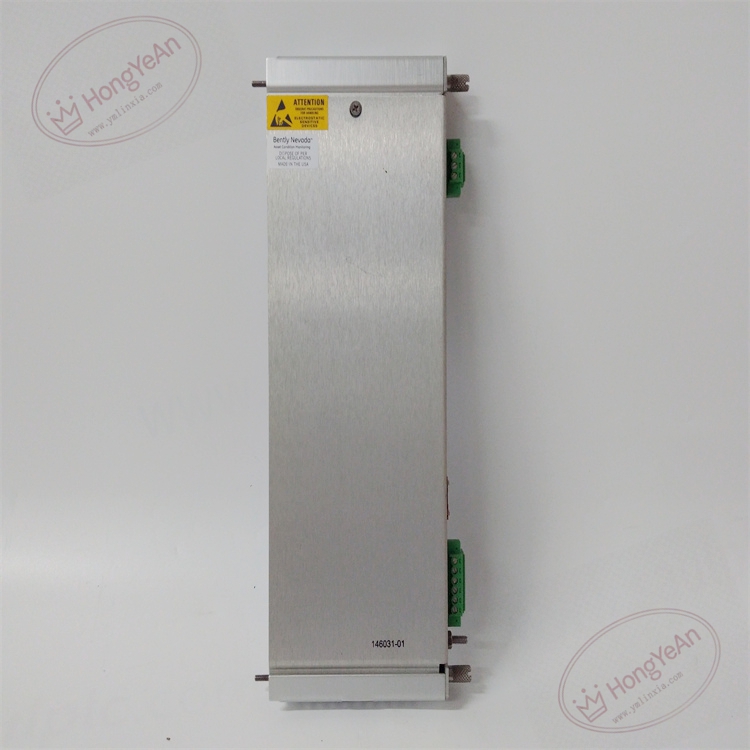
- Mechanical Form: Standard 3500‑series rear small‑card footprint; net weight approx. 0.43 kg; fits standard rear full‑height slot dimension
- Environmental Ratings: Operating temperature −30 °C ~ +65 °C; storage temperature −40 °C ~ +85 °C; relative humidity 5‑95 % non‑condensing; vibration and shock performance complies with API‑670 machinery‑protection industry standard
- Electrical Characteristics: Powered entirely via rack backplane 5 VDC supply; no local CPU or data‑acquisition chip. All transient‑data processing, protocol conversion and rack‑health judgment logic are fully executed on the 3500‑22M front‑end TDI module. This rear card purely completes hardware‑level signal bridging between rack internal backplane communication bus and external copper ethernet network, and drives rack‑OK relay status output. It does not participate in vibration, speed or position protection decision‑making logic.
- Communication Physical Layer Support: 10/100BASE‑TX auto‑negotiation copper Ethernet interface; differ from 146031‑02 fiber‑optic variant without optical transceiver circuit.
Core Functions
- Acts as physical external‑communication interface for 3500‑22M TDI module. Converts rack internal backplane communication signals to standard copper Ethernet signals, realizing bidirectional data transmission between TSI rack and upper‑level System‑1 condition‑monitoring host, 3500 configuration software and maintenance workstation.
- Carries rack‑OK dry‑contact relay output driven by overall rack diagnostic status. Relay changes state when rack‑wide hardware faults, module failures or power anomalies occur, provides remote fault‑annunciation signal for plant DCS or alarm system. This relay is only for warning purpose and shall not be connected to machinery protection trip loops.
- Transmits steady‑state measurement values, alarm status, system event log and module diagnostic codes out of rack via Ethernet. Dynamic waveform and high‑resolution transient data acquisition function depends on optional channel‑enable license disk configured on front‑end 3500‑22M module; rear‑card hardware itself does not restrict data‑capture capability.
- No local decision‑making or diagnostic logic. All communication error detection, rack‑health status evaluation and relay‑drive conditions are processed by 3500‑22M front‑end TDI module. Communication and rack‑fault status will be uploaded to system event log for operator troubleshooting review. This TDI small‑card belongs to non‑protection‑critical communication path; its failure will not affect normal hardware protection trip action of other monitor modules inside rack.
- Widely deployed in steam‑turbine, gas‑turbine and centrifugal‑compressor TSI machinery‑protection systems. Realizes condition‑monitoring data export for rotating‑equipment diagnostic analysis. Distinguished from other variants: 146031‑01 is standard copper‑ethernet version; 146031‑02 is fiber‑optic I/O small‑card for long‑distance anti‑EMI scenario; 146031‑03 / 146031‑04 adopt gold‑plated relay contacts for low‑energy signal switching application.
Installation Requirements
- Strict one‑to‑one slot‑pairing requirement: this rear small card must be inserted in rear slot‑1 directly behind 3500‑22M front‑end TDI module adjacent to rack power supply. Mismatched front‑rear part numbers or wrong slot positions will cause total loss of external ethernet communication and rack‑OK relay output. Each 3500 rack only needs one set of TDI front‑rear combination.
- Power‑off operation rule for rear‑card replacement: although front‑end monitor modules support hot‑swap function, insertion / extraction of this rear‑side communication small‑card must be performed with the entire 3500 rack powered down. Live‑swap of rear card may generate backplane bus transient noise, trigger temporary communication drop‑out and false rack‑OK relay action.
- Network cabling specification enforcement: use shielded twisted‑pair ethernet cable for RJ45 connection. Network cable shall be physically separated from high‑voltage power cables and large‑current motor cables to suppress electromagnetic interference, avoiding intermittent packet‑loss and communication drop‑out. Do not connect rack‑OK relay contacts to machine emergency‑trip circuit; only use for alarm annunciation. Verify relay contact load rating before connecting external annunciator circuit.
- Cabinet environmental control: maintain sufficient cabinet forced‑air ventilation and temperature control. Prevent oil mist, corrosive gas, conductive dust and moisture condensation inside cabinet space. Contamination accumulation on PCB traces and backplane connector pins will produce high‑resistance contact points and degrade long‑term communication stability and relay‑contact reliability.
- Pre‑installation visual inspection: carefully inspect backplane edge‑connector pins before inserting small card. Check for bent pins, mechanical deformation, corrosion, oil contamination and foreign‑object debris. Damaged or contaminated backplane contacts will result in intermittent ethernet link failure or abnormal rack‑OK relay operation, bringing sporadic hard‑to‑reproduce communication faults.
- Part‑number cross‑version distinction: 146031‑01 is standard copper‑ethernet TDI rear I/O small‑card; 146031‑02 is fiber‑optic variant; 146031‑03 copper with gold‑contact relay; 146031‑04 fiber with gold‑contact relay. These variants are not interchangeable on‑site; mixing‑up will cause interface mismatch or relay‑contact performance degradation.
Common Failure Modes
‑ RJ45 port or relay terminal oxidation / crimp degradation: intermittent ethernet link drop‑out, high packet‑loss rate, unstable rack‑OK relay switching. ‑ Backplane edge‑connector pin mechanical damage, bent or corroded contacts: complete loss of ethernet communication, rack‑OK relay keeps fixed state without status response. ‑ Conformal‑coating scratch, PCB trace corrosion induced by oil mist or chemical vapor: individual signal‑trace open‑circuit or short‑circuit inside PCB substrate, permanent failure of ethernet channel or relay‑drive circuit. ‑ ESD electrical overstress damage during field handling: internal PCB signal‑trace micro‑fracture or subtle copper‑layer damage without obvious exterior physical damage; manifests as unstable communication performance after cabinet internal thermal temperature cycling. ‑ Mechanical damage caused by improper insertion force: edge‑connector pin offset, internal fine‑trace cracking; communication or relay function fails under cabinet‑base vibration operating conditions
-300x300.jpg)
Reviews
There are no reviews yet.