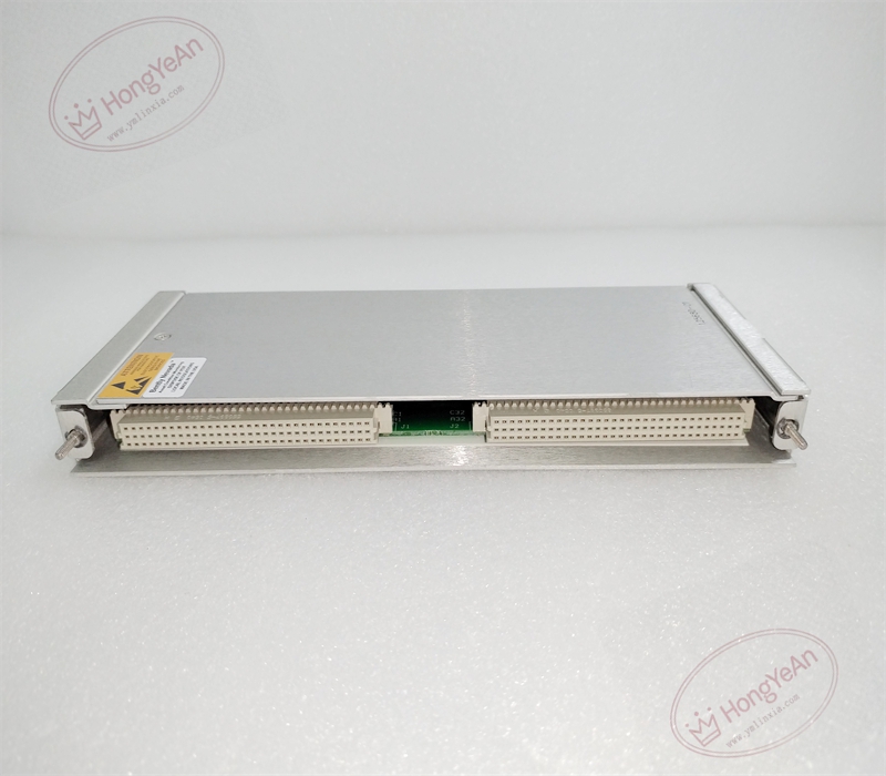
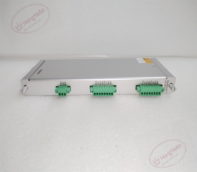
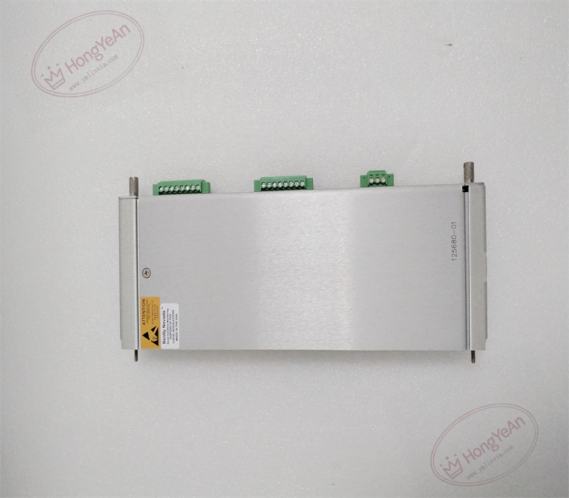
Description
Hardware & Electrical Specifications
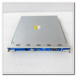
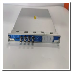
‑ Manufacturer: Bently Nevada (Baker Hughes) ‑ Device Type: 3500/40M Proximitor Internal‑Termination Rear I/O Module ‑ Number of Channels: 4 non‑isolated proximity transducer input channels ‑ Transducer Excitation: ‑24 Vdc power supply for proximitor sensors ‑ Input Impedance: 10 kΩ per channel ‑ Termination: Built‑in multi‑position screw terminal blocks for field‑signal wiring ‑ Backplane Interface: 3500 proprietary backplane connection mating with front 3500/40M monitor module ‑ Power Consumption: 7.7 W typical ‑ Mounting: Full‑height rear slot inside 3500‑series rack chassis ‑ Physical Dimension: 241.3 mm × 24.4 mm × 99.1 mm ‑ Weight: Approx 0.38 kg ‑ PCB Treatment: Conformal‑coated printed‑circuit board ‑ Operating Temperature: ‑30 ℃ ~ +65 ℃ ‑ Storage Temperature: ‑40 ℃ ~ +85 ℃ ‑ Certifications: CE, CSA, ATEX hazardous‑area approvals, API‑670 compliant
Environmental Specifications
‑ Relative Humidity: 5%‑95 %, non‑condensing ‑ Vibration Resistance: Meets industrial cabinet vibration requirements ‑ EMI Immunity: On‑board filtering suppresses electromagnetic crosstalk from power cables and variable‑frequency drives
Core Functions
- Transducer power feeding: Provides regulated‑24 Vdc excitation power for four‑channel proximitor‑probe‑extension‑cable assemblies.
- Field‑signal termination: Integrated screw terminals eliminate external termination panels, directly connecting field proximity transducer wiring to the 3500 monitoring rack.
- Analog signal routing: Delivers raw gap‑related analog signals from proximitors through backplane to front‑side 3500/40M main monitor for measurement computation.
- Sensor‑loop diagnostics: Detects open‑circuit, short‑circuit and abnormal impedance faults on each transducer channel, reports loop‑fault status to front monitor for system alarming.
- Multi‑parameter measurement support: Works cooperatively with front 3500/40M monitor to realize radial‑vibration, thrust‑position, differential‑expansion, eccentricity and REBAM measurement for rotating machinery.
Installation, Replacement & Critical Warnings
- This rear I/O module supports hot‑swap operation. Rack main power can remain energized during module replacement, but relevant field sensor wiring shall be de‑energized before terminal modification.
- Compatibility warning: ‑ Strictly matched with front‑side 3500/40M main monitor module; cannot pair with 3500/40 non‑M‑series monitor. ‑ The total electrical length of probe‑plus‑extension‑cable must match the calibrated length of the 3300‑XL transducer system. Random modification of cable assembly is prohibited. ‑ Route transducer signal cables separately from high‑voltage power cables and variable‑frequency‑drive output cables to reduce inductive interference. ‑ Tighten terminal screws to proper torque to avoid poor contact; prevent strand‑wire debris from falling into connectors. ‑ Inspect backplane connector pins for bending, dirt and corrosion before inserting the module into rear slot.
- Post‑replacement commissioning and verification: ‑ Confirm module is correctly seated in rear slot and backplane connection is reliable. ‑ Observe front‑panel status LED of paired 3500/40M monitor; no hardware‑fault or loop‑fault alarm under normal condition. ‑ Perform static gap calibration for each channel, verify displacement‑related readings change linearly with physical gap variation. ‑ Simulate transducer open‑circuit and short‑circuit conditions, confirm loop‑fault alarm triggers correctly. ‑ Under machine operating conditions, confirm vibration and position measurements are stable without jumping or drifting.
-300x300.jpg)
Reviews
There are no reviews yet.