Description
Hardware & Electrical Specifications
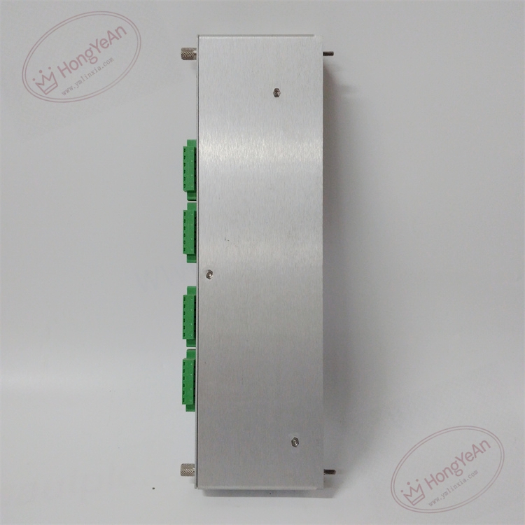
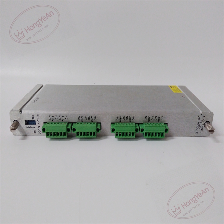
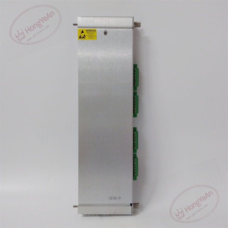
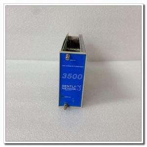
‑ Manufacturer: Bently Nevada (Baker Hughes) ‑ Device Type: 3500/32M 4‑Channel Relay Rear I/O Module ‑ Number of Relay Output Channels: 4 independent relay dry‑contact channels ‑ Contact Configuration: Form‑C change‑over contacts for each channel ‑ Contact Rating (Resistive Load): Max 2 A @ 30 Vdc; Max 2 A @250 Vac; maximum 450 VA ‑ Contact Life: 100 000 cycles at rated load ‑ Hardware Selection: On‑board switch for Normally‑Energized / Normally‑De‑energized mode per channel ‑ Termination: Screw‑type terminal blocks for field external‑circuit wiring ‑ Backplane Interface: 3500 proprietary backplane mating with front‑side 3500/32M main module ‑ Power Consumption: 5.8 W typical ‑ Mounting: Full‑height rear slot inside 3500 rack chassis ‑ PCB Treatment: Conformal‑coated printed‑circuit board ‑ Operating Temperature: ‑30 ℃ ~ +65 ℃ ‑ Storage Temperature: ‑40 ℃ ~ +85 ℃ ‑ Certifications: CE, CSA, ATEX hazardous‑area approvals, API‑670 compliant
Environmental Specifications
‑ Relative Humidity: 5%‑95 %, non‑condensing ‑ Vibration Resistance: Complies with industrial cabinet vibration requirements ‑ EMI Immunity: On‑board filtering reduces interference from heavy‑current and variable‑frequency‑drive circuits
Core Functions
- Relay‑contact signal termination: Provides field‑wiring screw terminals for four‑channel relay change‑over contacts, connecting the 3500 system alarm outputs to external interlock and annunciator equipment.
- Alarm‑logic execution interface: Receives voting‑logic results from front‑side 3500/32M module, drives relay action according to configured alert, danger, Not‑OK and PPL status from other monitor channels within the rack.
- Hardware relay mode selection: Each channel can be locally set to Normally‑Energized or Normally‑De‑energized to satisfy fail‑safe protection design requirements.
- Backplane signal transmission: Communicates relay status and module diagnostic information between rear I/O card and front‑panel 3500/32M monitor via rack backplane bus.
- External‑system interconnection: Delivers dry‑contact alarm signals for machinery early‑warning and protection interlock to DCS, PLC, local alarm annunciators and trip logic circuits.
Installation, Replacement & Critical Warnings
- This rear I/O module supports hot‑swap. Rack power may remain energized for module replacement, but external high‑voltage load circuits connected to relay terminals must be de‑energized before wiring modification.
- Compatibility warning: ‑ Strictly matched with front‑side 3500/32M main relay module; cannot pair with non‑M‑series 3500/32 hardware. ‑ External load must not exceed relay contact voltage and current rating; over‑rating will permanently damage relay contacts. ‑ Inductive loads (coils, contactors) connected to relay outputs require external free‑wheel suppression components to suppress back‑EMF. ‑ Separate relay‑output field cables from low‑level transducer signal cables to avoid inductive interference into vibration‑measurement loops. ‑ Tighten terminal screws to proper torque to prevent loose connections; avoid stray wire strands inside terminal block. ‑ Inspect backplane connector pins for bending, debris and corrosion before inserting module into rear slot.
- Post‑replacement commissioning and verification: ‑ Confirm module is fully seated in rear slot with reliable backplane connection. ‑ Check front‑panel status LED of paired 3500/32M monitor; no hardware‑fault indication under normal condition. ‑ Configure alarm‑drive voting logic and relay energize mode via 3500 rack configuration software. ‑ Simulate alarm conditions from related monitor channels, verify corresponding relay channels switch state correctly. ‑ Verify external annunciator, PLC or interlock circuit responds properly to relay contact state change.
-300x300.jpg)

Reviews
There are no reviews yet.