Description
Hardware & Electrical Specifications
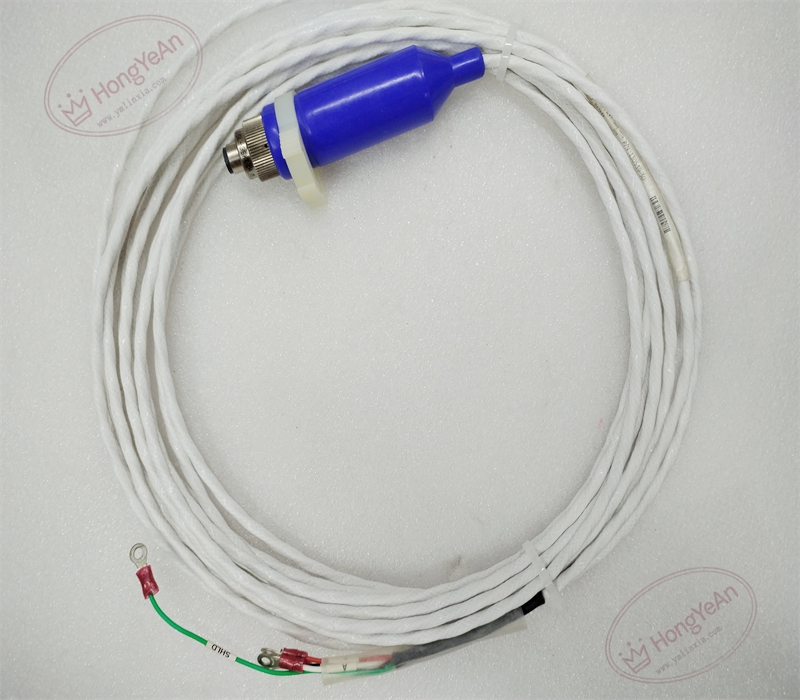
‑ Manufacturer: Bently Nevada (Baker Hughes) ‑ Device Type: Seismic Sensor Interconnect Cable Assembly ‑ Total Length: 30 ft (≈9.14 m) ‑ Wire Gauge: 18 AWG (1.0 mm²), 3‑conductor overall shielded construction ‑ Connector End: 3‑socket male‑style plug with fluorosilicone splash‑resistant boot ‑ Field Termination End: Pre‑crimped ring terminal lugs ‑ Cable Jacket: Splash‑resistant fluorosilicone elastomer material ‑ Operating Temperature: ‑40 ℃ ~ +85 ℃ ‑ Storage Temperature: ‑55 ℃ ~ +125 ℃ ‑ Shielding: Overall copper braid shield for noise suppression ‑ Certifications: Meets industrial rotating‑machinery monitoring requirements, API‑670 compliant
Environmental Specifications
‑ Relative Humidity: 5%‑95 %, non‑condensing ‑ Mechanical Properties: Resists splash, moderate oil and chemical exposure; not for continuous submerged service ‑ EMI Immunity: Overall braided shield reduces conducted and radiated electromagnetic interference
Core Functions
- Seismic‑sensor signal transmission: Transmits low‑level dynamic velocity / acceleration signals from Velomitor or accelerometer sensors to system termination panels or monitor rear‑I/O terminals.
- Physical sensor interconnection: Provides factory‑terminated cable assembly to connect seismic transducers to monitoring hardware, eliminating field‑side cable stripping and crimp errors.
- Environmental protection: Splash‑resistant fluorosilicone boot and jacket protect connection points against onsite moisture, oil mist and minor liquid splashes in turbine‑compressor environments.
- Noise suppression: Continuous overall shield maintains signal integrity for small‑amplitude vibration signals in high‑EMI industrial plant environments.
Installation, Replacement & Critical Warnings
- This is a passive field cable assembly; power‑down sensor‑side equipment before disconnecting either end of the cable.
- Compatibility warning: ‑ Exclusively for Bently Nevada seismic transducers (Velomitor, accelerometer); not compatible with 3300‑XL proximity probe systems. ‑ Do not cut or shorten this factory‑assembled cable; altering cable length changes electrical characteristics and impairs measurement performance. ‑ Route vibration signal cables separately from high‑voltage power cables, motor and variable‑frequency‑drive power wiring to avoid signal corruption. ‑ Secure strain relief at both ends; avoid sharp bending, pulling or crushing the cable jacket. ‑ Connect cable shield single‑point grounding per Bently installation instructions; multi‑point grounding will create ground‑loop noise.
- Post‑replacement commissioning and verification: ‑ Inspect plug boot, cable jacket and terminal lugs for mechanical damage. ‑ Secure 3‑pin plug fully locked onto the seismic sensor connector; torque ring lugs firmly onto terminal‑block studs. ‑ Perform cable continuity and insulation resistance check. ‑ Under machine operating conditions, verify stable seismic‑vibration amplitude readings without excessive jitter or noise.
-300x300.jpg)
Reviews
There are no reviews yet.