.jpg "本特利-133819-02.(1)")
.jpg "本特利-133819-02.(2)")
Description
.jpg)
Core technical features
- Six independent temperature input channels, supports multiple types of thermocouples (E, J, K, T) and platinum/nickel/copper RTD sensors.
- Non‑isolated internal termination design; field sensor cables directly land on module built‑in terminals without extra intermediate terminal blocks. Each channel provides 4‑20 mA recorder output for DCS data acquisition.
- Power is supplied via 3500 rack backplane. Module passes raw sensor signals to front 3500/61 board, all threshold‑judgment and fault‑diagnosis logic runs on front monitor card.
- Operating ambient: 0℃ ~ +60℃; storage‑40℃ ~ +85℃; humidity 5‑95% non‑condensing; cabinet rear‑side installation.
- Compatibility note: Only works with 3500/61 front monitor module. Cannot substitute isolated‑version I/O hardware. After replacement, verify sensor type setup inside 3500 configuration software, wrong parameter will bring large temperature reading deviation.
Physical construction
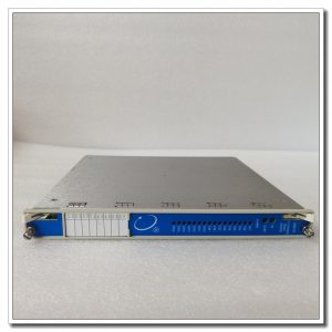
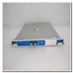
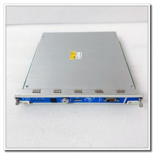
Single‑slot rear‑access plug‑in hardware for 3500 rack. Multiple screw‑type field‑wiring terminals distribute on module surface. Gold‑plated rear connector mates with rack backplane to communicate with front‑side 3500/61 board. Part‑number 133819‑02 is marked on module sticker. PCB is conformal‑coated against dust and trace corrosive gas inside power‑plant cabinet.
Field‑based practical notes
Widely fitted on steam and gas turbine 3500 monitoring racks. It collects bearing metal temperature, casing temperature from RTD / TC sensors. Rear I/O module failure leads to loss of temperature acquisition for all six channels. The front‑side monitor will generate channel fault alarms. During replacement, cut off rack power and follow ESD protection rules. Fasten every sensor wiring screw firmly. After power‑on, download valid 3500 configuration, check each channel temperature reading, clear event log before commissioning.
Installation & maintenance reminders
Keep thermocouple / RTD signal cables separated from high‑power cables to avoid electromagnetic interference. Pay attention to cold‑junction compensation for thermocouple loops. Backup 3500 system configuration file before hardware swap. On‑site component‑level repair is forbidden. Replace full rear‑module assembly for permanent hardware damage.
Typical on‑site fault phenomena
- Temperature reading shows zero or full‑scale overrange: Check sensor cable open‑circuit / short‑circuit condition, inspect terminal screw tightness.
- All six channels report fault: Confirm reliable backplane contact and mating 3500/61 front‑board status.
- Reading drift and instability: Check cabinet temperature environment, cable shielding grounding and terminal oxidation.
- Channel reading offset: Verify sensor type parameter matches actual field device.
-300x300.jpg)
Reviews
There are no reviews yet.