Description
Hardware Specifications
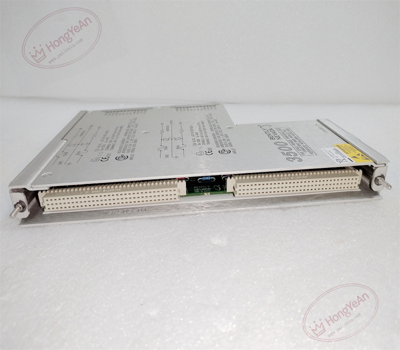
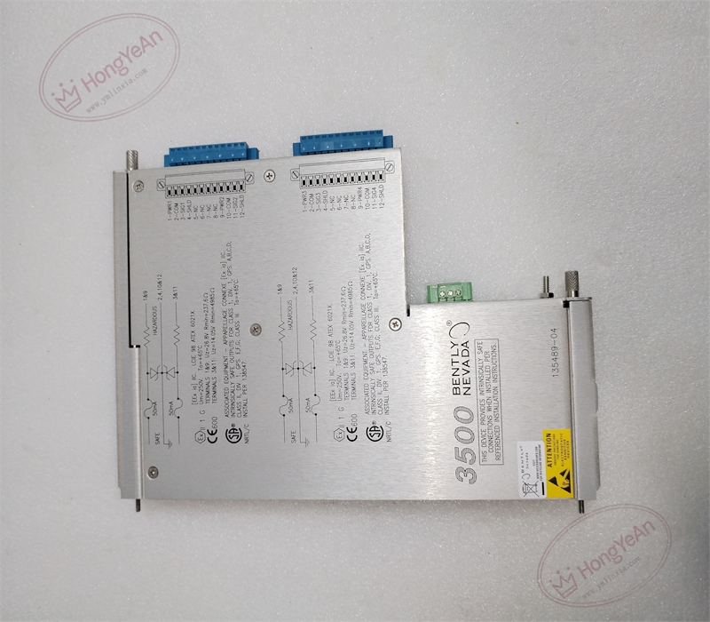
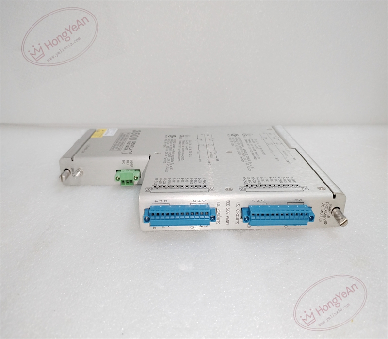
- Part Type: Rear I/O small card with internal intrinsic‑safety barriers, dedicated pairing for 3500‑40M front‑end proximitor monitor, standalone operation is prohibited
- Mounting: Rear slot position of the 3500‑05 system rack, front‑rear separated architecture
- Termination: On‑board built‑in screw terminals; external terminal adapter is not required. Supports four‑channel proximity probe transducer interfaces
- Safety Feature: Integrated intrinsic‑safety barriers to limit energy delivered to field hazardous‑area proximity circuits, satisfies intrinsic‑safety installation requirements for classified explosive zones
- PCB: Conformal‑coated multilayer printed circuit board for harsh industrial environments
- Mechanical: Standard 3500‑series rear small‑card form factor, net weight approx. 0.46 kg
- Environmental: Operating temperature ‑30 ℃ ~ +65 ℃; storage temperature ‑40 ℃ ~ +85 ℃; vibration and shock performance complies with API‑670 machinery protection standard
- Electrical: Receives proximitor‑18 V /‑24 V excitation power from front‑end module; barrier circuits clamp voltage and current for field‑side hazardous‑area loops; no on‑board microprocessor for signal processing or logic judgment.
Core Functions
- Serves as the physical field‑wiring interface for the 3500‑40M proximitor monitor, distributes intrinsically‑safe excitation power to proximity probes and transmits four‑channel shaft displacement measurement signals to the paired front‑end processing module.
- Internal intrinsic‑safety barriers restrict electrical energy on field instrument loops, allowing proximity probes to be deployed in hazardous‑area locations when wiring strictly complies with intrinsic‑safety installation specifications.
- Supports radial shaft vibration, thrust position and eccentricity measurement applications. All channel sensitivity configuration, alarm / danger threshold setup and sensor diagnostic logic are completed on the 3500‑40M front‑end module. This rear card only implements hardware‑level power distribution and signal routing.
- Contains no local processing logic; all sensor fault detection, signal anomaly diagnosis and alarm generation are executed by the front‑end monitor, and fault status is uploaded to the 3500 system host for display.
- Applied for rotating‑machinery protection on steam turbines, gas turbines and centrifugal compressors, monitoring shaft radial vibration and axial thrust position to prevent rotor‑stator rubbing failures.
Installation Requirements
- Mandatory one‑to‑one slot matching with compatible 3500‑40M front‑end module. Mismatched front‑rear part numbers will cause invalid measurement readings, loss of transducer excitation power or failure of intrinsic‑safety protection performance.
- Perform insertion‑removal operations under rack power‑off condition. Although front‑end modules support hot‑swap, rear I/O small‑card replacement shall be carried out with power cut‑off, to avoid transient electrical spikes that may damage field proximity probes or degrade barrier circuit performance.
- Field wiring must strictly follow intrinsic‑safety drawing specifications. Apply proper torque for screw terminals; loose connections will produce vibration reading drift, intermittent signal jumps and false machinery protection alarms.
- Maintain sufficient cabinet ventilation. Avoid direct exposure to corrosive gas, oil mist and conductive dust to prevent PCB trace corrosion and terminal oxidation.
- Inspect backplane connector pins before installation. Bent, contaminated or corroded pins may result in partial‑channel dropout or complete loss of transducer excitation power.
- Do not modify components of internal barrier circuits. Replacement must use identical part number to preserve intrinsic‑safety certification validity.
Common Failure Modes
‑ Terminal oxidation or crimp degradation: intermittent vibration‑value jump and floating measurement readings. ‑ Backplane contact pin damage: partial or total channel loss, loss of proximitor excitation supply. ‑ Conformal coating damage / PCB trace corrosion: short‑circuit or open‑circuit of individual signal channels, degradation of intrinsic‑safety barrier performance. ‑ Mechanical damage during handling: internal trace breakage without obvious surface damage; barrier component failure induced by electrical overstress.
Reviews
There are no reviews yet.