Description
Hardware Specifications
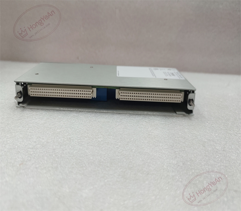
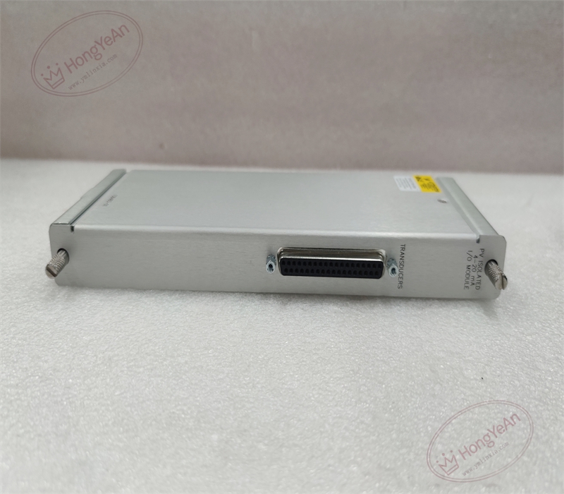
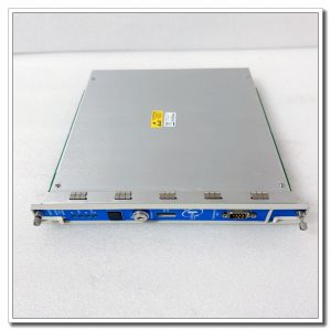
- Part Type: Rear I/O small card with channel‑level galvanic isolation, external‑termination style, dedicated pairing for 3500‑62 front‑end process variable monitor, standalone operation invalid
- Mounting: Rear slot position of 3500‑05 rack, front‑rear paired‑slot architecture, directly installed behind 3500‑62 front‑end monitor module
- Termination: No built‑in screw terminals on small‑card body; signal connections are realized via external termination adapter assembly, supporting six‑channel 4‑20 mA analog current input loops
- Isolation Performance: Each measurement channel provides independent galvanic isolation between field transmitter side and rack backplane side, suppresses common‑mode noise and ground‑loop interference generated by multi‑point distributed field instruments
- PCB: Conformal‑coated multi‑layer FR‑4 PCB, delivers anti‑corrosion protection for long‑term running under oily, dusty industrial cabinet environment
- Mechanical Form: Standard 3500‑series rear small‑card footprint; net weight approx. 0.44 kg; fits standard rear full‑height slot dimension
- Environmental Ratings: Operating temperature −30 °C ~ +65 °C; storage temperature −40 °C ~ +85 °C; relative humidity 5‑95 % non‑condensing; vibration and shock performance complies with API‑670 machinery‑protection industry standard
- Electrical Characteristics: Fully powered through rack backplane 5 VDC supply; no local CPU, signal‑conditioning chip or alarm‑judgment circuit. All analog signal sampling, range configuration, alarm / danger threshold setup and channel diagnostic processing are fully executed on the 3500‑62 front‑end monitor module. This rear card only completes isolated hardware‑level signal routing between rack internal backplane traces and external termination adapter. Loop power for 4‑20 mA transmitters must be supplied by external site power source, and this card cannot provide field loop power supply.
- Input Signal Range: Accepts standard industry 4‑20 mA current analog signals from two‑wire or four‑wire process transmitters.
Core Functions
- Acts as intermediate signal transfer interface for 3500‑62 process variable monitor. Six‑channel 4‑20 mA analog signals from field pressure transmitters, flow transmitters, liquid‑level transmitters and other process instruments are transmitted to front‑end processing module through external termination adapter and this rear small‑card internal circuit for analog‑digital conversion.
- Independent channel‑by‑channel galvanic isolation restrains common‑mode interference and eliminates ground‑loop risks existing among multi‑point distributed field instruments, improving overall measurement stability of process‑variable acquisition system. Adopting external termination mode, field wiring is completed on separate adapter component, which avoids repeated disassembly of rear small‑card during field wiring maintenance and modification work.
- Supports continuous monitoring of critical auxiliary process parameters for rotating equipment, including compressor suction‑discharge pressure, lube‑oil system pressure, process medium flow and tank liquid‑level. All channel type selection, measurement range definition and alarm logic configuration are finished in 3500 rack configuration software on front‑end module; this rear I/O hardware does not participate in parameter operation and calculation.
- No local decision‑making or diagnostic logic. All transmitter fault detection, signal over‑range / under‑range identification and fault‑code generation are processed by 3500‑62 front‑end monitor. Fault status information will be uploaded to 3500 system host and recorded in system event log for operator troubleshooting review.
- Widely deployed in steam‑turbine, gas‑turbine and centrifugal‑compressor TSI protection systems. Realizes integration of process‑variable signals into machinery‑protection platform, supports interlock trigger conditions based on process‑parameter deviation, and complements traditional vibration and position protection functions. Distinguished from 136294‑01 internal‑termination variant, this model relies on external adapter for field wiring; it also differs from 137110‑01 intrinsic‑safety barrier‑type small card without energy‑limiting circuit for hazardous‑area application.
Installation Requirements
- Strict one‑to‑one slot‑pairing requirement: this rear small card must be inserted in the rear slot directly behind a 3500‑62 front‑end process‑variable monitor module. Mismatched front‑rear part numbers or misaligned slot positions will cause channel reading anomalies, signal isolation failure or complete loss of analog input channels. Meanwhile, matched external termination adapter assembly shall be adopted; mismatched adapter will lead to channel disconnection.
- Power‑off operation rule for rear‑card replacement: although front‑end modules support hot‑swap function, rear‑side I/O small‑card insertion / extraction must be performed with the entire 3500 rack powered down. Live‑swap of rear card may generate backplane bus transient noise, induce transient current disturbance on 4‑20 mA loops, produce temporary jump of measured values and trigger false alarm events on 3500 system and upper‑level DCS. Field wiring modification can be operated on external termination adapter without pulling out rear small‑card.
- Field‑loop wiring specification enforcement: use shielded twisted‑pair cables for all 4‑20 mA field instrument wiring. Cable shielding layers shall implement single‑end grounding at control‑system cabinet ground bar. Instrument cables must be physically separated from high‑voltage AC power cables and large‑current motor cables to suppress electromagnetic interference. Confirm external loop power polarity matches adapter terminal definition, reverse‑polarity connection will lead to channel non‑response. Apply proper torque for adapter screw terminals; loose terminal connections will produce measurement drift, intermittent signal jumping and spurious alarms.
- Cabinet environmental control: maintain sufficient cabinet forced‑air ventilation and temperature control. Prevent oil mist, corrosive gas, conductive dust and moisture condensation inside cabinet space. Contamination accumulation on PCB traces and connector pins will produce high‑resistance contact points and degrade long‑term measurement stability and isolation performance.
- Pre‑installation visual inspection: carefully inspect backplane edge‑connector pins before inserting the small card. Check for bent pins, mechanical deformation, corrosion, oil contamination and foreign‑object debris. Damaged or contaminated backplane contacts will result in partial‑bit data corruption, sporadic non‑reproducible measurement faults difficult to locate during routine maintenance. Inspect contact status between small‑card and external termination adapter simultaneously.
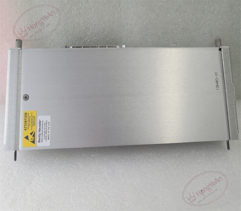
- Part‑number cross‑version distinction: 136483‑01 is external‑termination isolated 4‑20 mA I/O small card; 136294‑01 is internal‑termination isolated 4‑20 mA variant; 137110‑01 integrates intrinsic‑safety barrier circuits for hazardous‑location field loops. These variants are not interchangeable on‑site; mixing‑up will cause wiring incompatibility, loss of isolation or intrinsic‑safety certification failure.
Common Failure Modes
‑ Adapter terminal oxidation or crimp degradation: intermittent process‑value jump, floating measurement readings, random under‑range / over‑range channel alarms. ‑ Backplane edge‑connector pin mechanical damage, bent or corroded contacts: partial or total loss of analog input channels, abnormal isolated‑channel performance. ‑ Conformal‑coating scratch, PCB trace corrosion induced by oil mist or chemical vapor: individual signal‑trace open‑circuit or short‑circuit inside PCB substrate, degradation of galvanic‑isolation dielectric performance. ‑ ESD electrical overstress damage during field handling: internal PCB signal‑trace micro‑fracture or subtle copper‑layer damage without obvious exterior physical damage; manifests as unstable measurement performance after cabinet internal thermal temperature cycling. ‑ Mechanical damage caused by improper insertion force: edge‑connector pin offset, internal fine‑trace cracking; measurement channel failure occurs when equipment suffers cabinet‑base vibration; poor contact between small‑card and external termination adapter brings intermittent signal faults.
-300x300.jpg)
Reviews
There are no reviews yet.