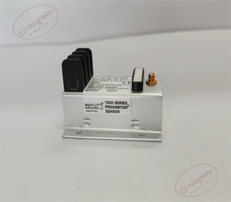
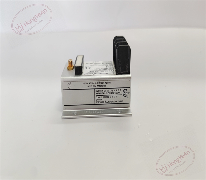
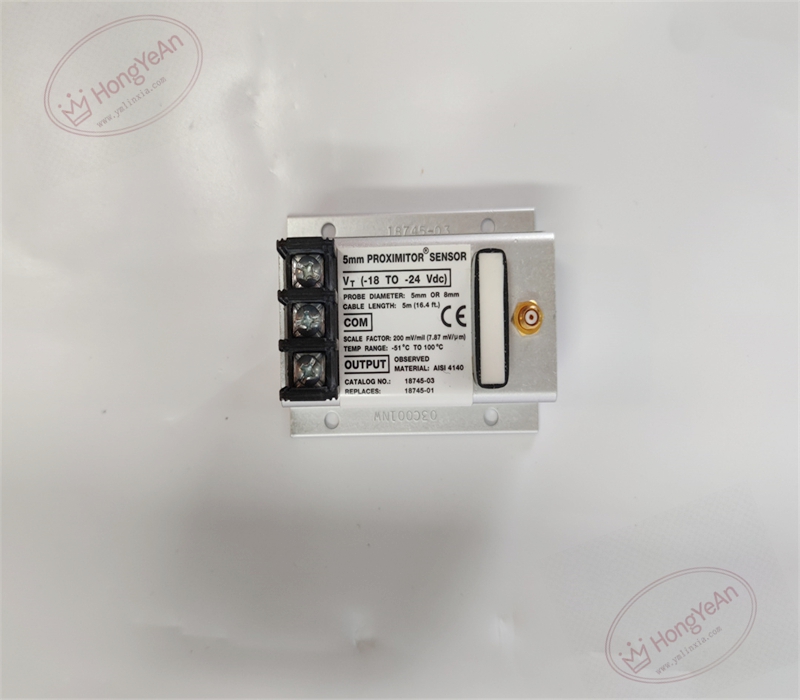
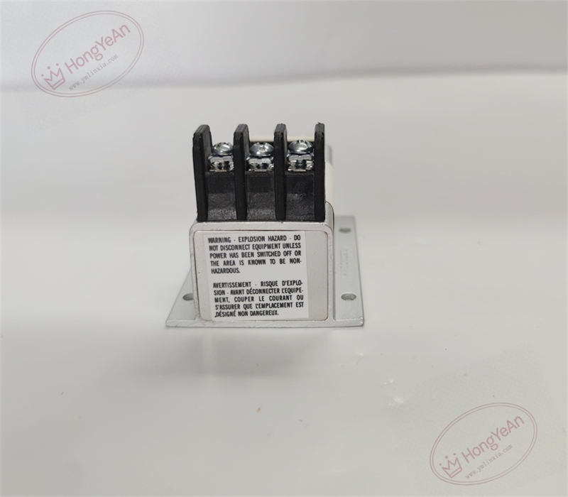
Description
Hardware & Electrical Specifications
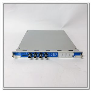
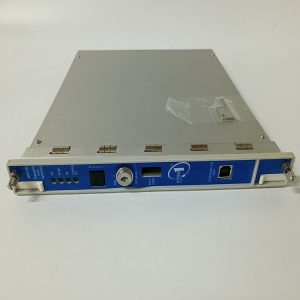
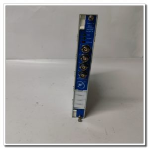
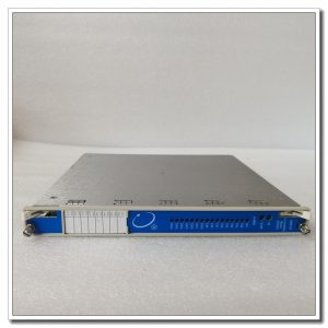
‑ Manufacturer: Bently Nevada (Baker Hughes) ‑ Device Type: 7200‑XL Eddy‑current Proximitor Sensor ‑ Compatible Probes: 5 mm, 8 mm eddy‑current proximity probes ‑ Power Supply: ‑24 Vdc ±1 V, maximum current consumption 30 mA ‑ Analog Output 1: 4‑20 mA, maximum load 750 Ω ‑ Analog Output 2: ±10 Vdc, minimum load 5 kΩ ‑ BNC Buffered Output Sensitivity: 7.87 V/mm (200 mV/mil), tolerance ±5 % ‑ Linear Accuracy: ≤ ±0.5 % full‑scale range ‑ Frequency Response: 0‑10 kHz (‑3dB) ‑ Operating Temperature: ‑30 ℃ ~ +85 ℃ ‑ Storage Temperature: ‑40 ℃ ~ +100 ℃ ‑ Mounting: DIN‑rail clip mounting ‑ Housing Material: Blue flame‑retardant engineering plastic ‑ Certifications: CE, UL, CSA Class I Div2, ATEX Zone 2 hazardous‑area approvals
Environmental Specifications
‑ Relative Humidity: 5%‑95 %, non‑condensing ‑ Vibration Resistance: Suitable for typical industrial cabinet vibration conditions ‑ EMI Immunity: Built‑in radio‑frequency interference suppression against variable‑frequency drives and power‑cable crosstalk
Core Functions
- Eddy‑current signal conditioning: Processes high‑frequency RF signals from probe‑extension‑cable assembly, converts physical gap changes between probe and target into standard industrial analog signals.
- Dual analog outputs: 4‑20 mA current output for long‑distance transmission to DCS/PLC; ±10 V voltage output for local instrument interfaces.
- BNC buffered test port: Delivers raw vibration waveform for on‑site waveform observation and troubleshooting with oscilloscope.
- Probe loop self‑diagnosis: Continuously detects open‑circuit and short‑circuit faults of probe and extension cable, and provides loop‑fault status for system alarming.
- Non‑contact measurement: No mechanical wear, designed for long‑term online monitoring of high‑speed rotating shafts on turbines and compressors.
Installation, Replacement & Critical Warnings
- This is an active signal‑conditioning device, not hot‑swappable. Disconnect the ‑24 Vdc power supply before any wiring operation.
- The total calibrated system cable length (probe plus extension cable) must match the proximitor specification. Random replacement of extension cables with different lengths is prohibited.
- 5 mm and 8 mm probe types must match this proximitor; cross‑model mixing is not allowed.
- Mount on DIN‑rail inside cabinet, keep sufficient separation from high‑power contactors and variable‑frequency drives. Route signal cables separately from power cables.
- Tighten terminal screws to proper torque to avoid poor connections. Cap the unused BNC test port for protection.
- Power negative and signal ground shall follow single‑point‑grounding requirements per drawing to prevent ground‑loop noise.
Commissioning and Verification Criteria
- Confirm ‑24 Vdc power supply stays within tolerance range and wiring polarity is correct.
- Static gap calibration: Move probe target across working range, verify 4‑20 mA and ±10 V outputs follow gap variation with good linearity.
- Observe raw waveform via BNC port; waveform shall be clean without abnormal noise or glitches.
- Simulate probe open‑circuit and short‑circuit conditions to confirm loop‑fault alarm triggers properly.
- Under machine operating conditions, vibration and displacement readings remain stable without jumping or drifting.
Common Failure Modes and Symptoms
‑ Power supply abnormality: No output and faulty loop status; inspect ‑24 V power and wiring connections. ‑ Probe / extension‑cable open or short circuit: Proximitor reports loop fault, analog output saturates or holds fixed value. ‑ Mismatched total cable length: Degraded linear performance and overall reading offset. ‑ Ground‑loop interference: Waveform superimposed with power‑frequency noise and irregular reading fluctuation. ‑ Damaged BNC connector: Raw waveform observation fails, while 4‑20 mA and voltage outputs may still function normally.
Reviews
There are no reviews yet.