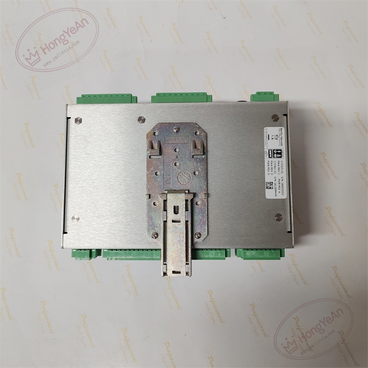
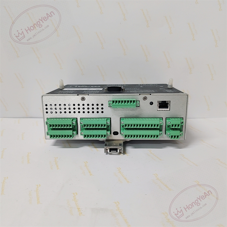
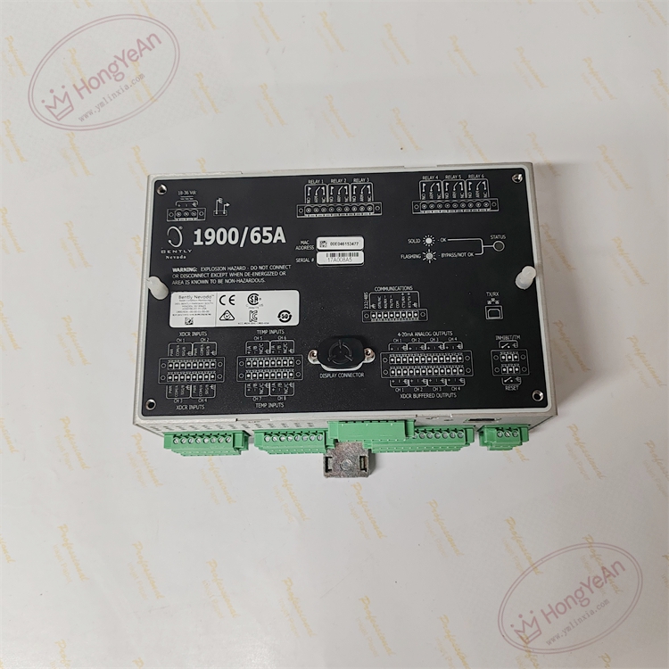
Description
Hardware & Electrical Specifications
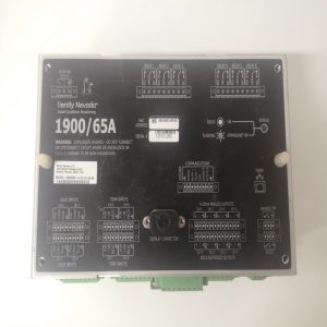
‑ Manufacturer: Bently Nevada (Baker Hughes) ‑ Compatible System: 1900 series machinery monitoring platform ‑ Functional Type: General‑Purpose Multi‑Input Machinery Monitor ‑ Input Channels: • 4 × configurable dynamic transducer inputs (proximity probe, accelerometer, velocity sensor, tachometer) • 4 × temperature inputs: RTD (2‑wire /3‑wire), Type E/J/K/T thermocouples ‑ Analog Output: 4 × isolated 4‑20 mA recorder outputs, freely assignable to measurement variables ‑ Relay Output: 6 × programmable SPDT relay contacts for Alert, Danger, module fault ‑ Diagnostics: Per‑channel open‑circuit / short‑circuit transducer fault detection; buffered BNC signal output per channel for waveform inspection ‑ Local Interface: LCD display + push‑button keypad for on‑site reading and setup ‑ Communication Interfaces: RJ45 Ethernet (Modbus‑TCP); RS232/RS485 software selectable serial port (Modbus‑RTU) ‑ Event Storage: 200‑entry fault event history buffer for post‑incident analysis ‑ Auxiliary Power: 18‑36 VDC wide‑range DC power supply ‑ Indicators: Multi‑LED array for power, module fault, channel alarm status ‑ Connectors: Removable screw terminal blocks for power, field I/O and communication; BNC buffered test ports; RJ45 Ethernet ‑ Mounting: 35 mm DIN‑rail or cabinet front‑panel cut‑out mounting ‑ Enclosure: Metal housing, IP20 ‑ Certification: ATEX / IECEx / FM Class I Div 2 hazardous‑location approval (order‑code dependent) ‑ Hot‑swap: Non‑hot‑swappable; de‑energize auxiliary DC power before hardware replacement ‑ Configuration Tool: 1900 Configuration Software for parameter download and firmware upgrade
Environmental Specifications
‑ Operating Temperature: ‑20 °C ~ +60 °C ‑ Storage Temperature: ‑40 °C ~ +85 °C ‑ Relative Humidity: 5%‑95 % non‑condensing ‑ Vibration & Shock: Complies with API‑670 and power‑plant cabinet EMC transient requirements
Mechanical Data
‑ Weight: approx 1.1 kg
Core Functions
- Multi‑parameter unified acquisition: Collects shaft vibration, thrust displacement, housing vibration, rotating speed and bearing‑temperature signals for auxiliary rotating‑machinery condition evaluationBaker Hugh…。
- Flexible two‑stage alarm supervision: Configurable Alert / Danger thresholds with adjustable time‑delay filter; latching / non‑latching relay mode selectable for suppressing nuisance alarms during machine startup.
- Multi‑form output interface: 4‑20 mA analog outputs transmit trending data to plant DCS/PLC; relay contacts output alarm signals to local annunciator.
- Digital gateway capability: Modbus‑TCP / Modbus‑RTU uploads real‑time measurements, alarm status and event logs to SCADA and System 1 condition‑monitoring software.
- On‑site troubleshooting support: Local LCD readout; BNC buffered ports output raw transducer waveform for oscilloscope inspection during commissioning and fault diagnosis.
Installation, Replacement & Critical Warnings
- De‑energize 18‑36 VDC auxiliary power before replacement. Unit is non‑hot‑swappable. Isolate field sensor wiring when servicing terminal blocks.
- Verify full order suffix matches site power and communication requirements; incorrect variant results in communication function missing.
- Configure transducer type, measurement range and alarm thresholds according to machinery OEM specification via 1900 configuration software; factory default parameters cannot be used for field operation.
- After installation, verify LCD readings, 4‑20 mA loop values, relay‑alarm action and Modbus data communication.
-
Common failure mode: Field‑wiring surge damage to input circuits. Investigate transducer cables and grounding when transducer‑fault alarms are triggered.

Reviews
There are no reviews yet.