Description
Hardware Specifications
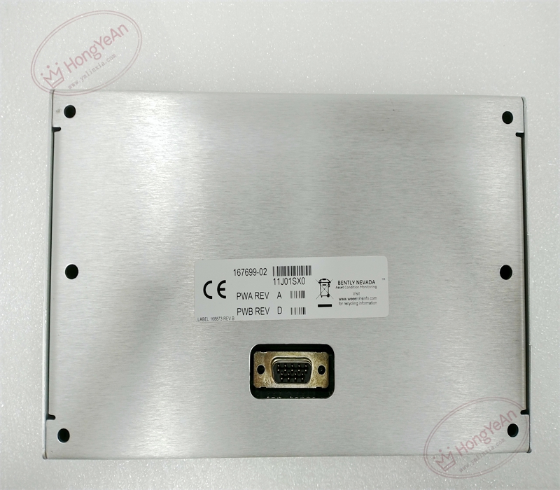
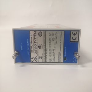
- Part Type: Stand‑alone general‑purpose machinery monitor base unit, DIN‑rail mounting, independent metal housing, not 3500‑05 rack slot‑mount hardware
- Mounting: Standard DIN‑rail installation inside control cabinet; front‑panel optional display keypad 172323‑01 can be panel‑mounted separately
- Termination: Multi‑group green plug‑in screw terminal blocks for transducer inputs, temperature inputs, relay outputs, 4‑20 mA analog outputs and power supply connection
- Power Supply: 85‑264 VAC, 47‑63 Hz wide‑range AC power input; internal power reverse‑polarity and surge protection circuit integratedabb-drive …
- I/O Resource: 4‑channel configurable transducer inputs (proximity, velocity, accelerometer); 4‑channel temperature inputs (RTD / Thermocouple); 6‑channel SPDT relay outputs; 4‑channel 4‑20 mA analog recorder outputs; buffered transducer signal output; optional Modbus‑RTU communication interface
- Mechanical Form: Compact metal‑shielded housing; net weight approx. 0.77 kg; dimension 196.9 × 149.4 × 74.4 mm
- PCB: Conformal‑coated multi‑layer FR‑4 PCB inside housing, anti‑corrosion for oily, dusty industrial cabinet environment
- Environmental Ratings: Operating temperature ‑40 °C ~ +70 °C; storage temperature ‑40 °C ~ +85 °C; relative humidity 5‑95 % non‑condensing; vibration and shock comply with industrial machinery‑monitoring equipment standardsabb-drive …
- Electrical Characteristics: Internal 24‑bit ADC signal acquisition circuit. Executes sensor signal conditioning, measurement conversion, Alert / Danger threshold comparison, sensor fault diagnosis and relay‑drive logic locally. Supports complete stand‑alone monitoring operation without upper‑level host. All channel configuration, scale‑factor setting, alarm‑threshold assignment are completed via 1900 configuration software or optional front‑side keypad module. Relay contacts can be configured as Normally‑Energized / Normally‑De‑energized fail‑safe mode for field project requirementbentlydcs ….
- Input Signal Support: Eddy‑current proximity probe, velocity sensor, accelerometer; 2‑wire / 3‑wire RTD; Type E/J/K/T thermocouple; mixed‑type channel configuration is allowed.
Core Functions
- Acts as complete stand‑alone monitoring unit for balance‑of‑plant rotating‑machinery, such as pumps, fans, blowers, small compressors and motors. Collects vibration, displacement and bearing‑temperature signals from field sensors, completes real‑time measurement and alarm judgment locally, outputs alarm status via relay dry‑contacts and 4‑20 mA analog signals to external DCS, PLC and annunciator systemsBaker Hugh….
- Supports flexible I/O configuration. Each transducer channel can be software‑assigned to different sensor types. Relay channels support combination voting logic based on Alert, Danger, module‑Not‑OK status of any measuring channel. Buffered output provides raw transducer waveform signal for on‑site portable diagnostic instrument connectionBaker Hugh….
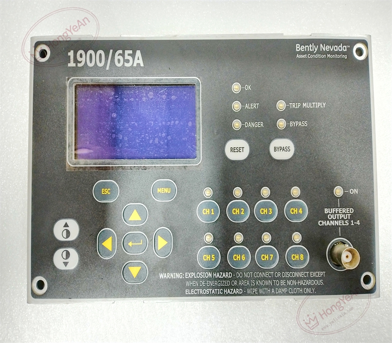
- Optional front keypad‑display module (172323‑01) connects to this base unit, realizes local on‑site data viewing, parameter modification and event‑log browsing without relying on configuration workstation. Modbus‑RTU communication option uploads measurement values, alarm status and event records to upper‑level monitoring host.
- Implements local sensor fault diagnosis: transducer open‑circuit, short‑circuit, signal‑out‑of‑range faults are detected inside base unit. Stores up to 200 groups of time‑stamped event log for maintenance troubleshooting. This hardware is designed for auxiliary equipment monitoring; for critical turbine TMR protection application, 3500‑series rack‑based protection system shall be adopted insteadabb-drive ….
- Widely deployed in power, petrochemical and manufacturing plants for non‑critical rotating‑equipment condition‑protection scenarios. Distinguished from combination parts: 167699‑02 is main monitor base unit; 172323‑01 is separate display‑keypad accessory; both must be matched to realize full local HMI function; cannot be interchanged with 3500‑series rack‑based modules.
Installation Requirements
- Mounting requirement: install base unit on DIN‑rail inside safe‑area control cabinet. Keep sufficient ventilation clearance around housing, avoid installation adjacent to high‑heat power components. This unit cannot be inserted into 3500‑05 rack slots. If equipped with keypad‑display module, complete separate panel‑mount installation for operator access.
- Power‑off operation rule for replacement: cut off AC power supply before wiring or module replacement. Live‑wiring may cause transient signal disturbance, false sensor‑fault diagnosis and random relay‑contact switching action.
- Field‑wiring specification enforcement: use shielded twisted‑pair instrument cables for sensor and signal wiring. Thermocouple loops must adopt matched compensating cables. Signal cables shall be physically separated from high‑voltage power cables and large‑current motor cables to suppress electromagnetic interference. Apply proper torque for plug‑in terminal‑block screws; loose connections generate signal jumping and random sensor‑fault alarms. Strictly observe relay‑contact load rating before connecting external interlock circuit.
- Cabinet environmental control: maintain good cabinet ventilation. Prevent oil mist, corrosive gas, conductive dust and moisture condensation. Contamination accumulation on internal PCB and terminals will increase contact resistance and degrade long‑term measurement stability and relay‑contact reliability.
- Pre‑installation visual inspection: inspect housing, terminal blocks and internal connectors before commissioning. Check for mechanical damage, pin bending and foreign‑object debris. Damaged terminals will bring sporadic hard‑to‑reproduce signal‑intermittent faults.
- Part‑number cross‑version distinction: 167699‑02 is main base unit for 1900‑65A monitor; 172323‑01 is matched display‑keypad accessory. Different firmware suffix revisions have channel‑function difference; cross‑replacement needs configuration software parameter re‑commissioning.
Common Failure Modes
‑ Plug‑in terminal‑block oxidation or crimp degradation: intermittent measurement‑value drift, random sensor open‑circuit / short‑circuit fault alarms, unstable relay‑switching action. ‑ Internal PCB circuit damage: partial‑channel or total loss of sensor signal acquisition, relay contacts keep fixed state without alarm‑status response. ‑ Conformal‑coating scratch, PCB trace corrosion induced by oil mist or chemical vapor: internal signal‑trace open‑circuit or short‑circuit, permanent failure of partial input / output channels. ‑ ESD electrical overstress damage during field‑handling: fine PCB trace micro‑fracture without obvious exterior damage; manifests as unstable measurement performance under cabinet temperature‑cycling. ‑ Mechanical damage caused by improper installation: housing deformation and internal connector pin deformation; measuring‑channel intermittent‑failure occurs under cabinet‑base vibration operating conditions.
-300x300.jpg)
Reviews
There are no reviews yet.