Description
Hardware Specifications
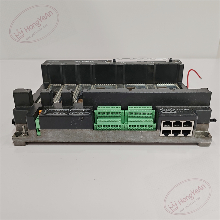
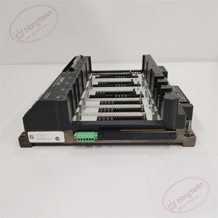
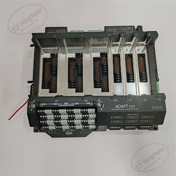
- Part Type: Safety system terminal base assembly, dedicated mating with 3701/55 ADAPT ESD controller main module, standalone operation invalid
- Mounting: Standard rack‑mount installation inside control cabinet; accepts multiple plug‑in I/O sub‑modules
- Termination: Multi‑group spring‑clamp screw terminal blocks for field sensor inputs, trip relay outputs, power supply and communication interfaces
- Power Supply: 24 VDC system power fed through base backplane; integrated ESD and surge protection circuitry on signal loops
- Mechanical Form: Metal‑reinforced rack housing; flame‑retardant insulating material for terminal sections
- PCB: Conformal‑coated multi‑layer FR‑4 backplane PCB, anti‑corrosion for industrial oily‑dusty cabinet environment
- Environmental Ratings: Operating temperature ‑40 °C ~ +70 °C; storage temperature ‑40 °C ~ +85 °C; relative humidity 5‑95 % non‑condensing; vibration and shock comply with safety‑system industry standards
- Electrical Characteristics: Backplane bus routes power, safety logic signals and communication between 3701/55 main controller and plug‑in I/O sub‑modules. All field circuits pass through ESD suppression components on base assembly. This unit executes only wiring interconnection and signal conditioning; safety logic, overspeed detection and trip decision are fully processed inside the paired 3701/55 main controller module. Safety certification SIL‑3 is valid only when complete matched hardware set is deployed.
- Signal Compatibility: Accepts proximity probe speed signals, discrete interlock inputs, analog 4‑20 mA process signals and trip relay output loops from field equipment.
Core Functions
- Acts as physical wiring and backplane interconnection foundation for 3701/55 ADAPT ESD emergency shutdown safety controller. Routes field‑side sensor and interlock signals to main controller module, and distributes trip, alarm and communication signals from controller to field devices.
- Built‑in ESD protective circuits suppress electrostatic surge interference on field wiring loops, reducing external disturbance impact on safety‑critical measurement and trip circuits. Supports hot‑swap of individual plug‑in I/O sub‑modules without powering down the whole base assembly.
- Multiple I/O sub‑modules can be inserted into base slots to expand channel quantity for overspeed monitoring, machinery interlock, analog process monitoring and trip output functions. All safety application logic, threshold comparison and fault diagnosis are performed on 3701/55 main controller, not on this terminal base.
- Provides mechanical positioning and locking structure for main controller and sub‑I/O modules; ensures reliable backplane contact under cabinet vibration conditions. System time‑stamped fault log is stored within paired 3701/55 main unit. For turbine critical protection, complete SIL‑3 system configuration must follow official application drawings.
- Widely applied in power, petrochemical and oil‑gas plants for steam‑turbine, gas‑turbine and large‑compressor safety shutdown protection scenarios. Distinguished hardware matching rule: 289761‑01 base must work together with 3701/55 main controller; cross‑replacement of base assembly requires full safety‑logic re‑commissioning and safety‑certification validation.
Installation Requirements
- Mounting requirement: install base assembly on standard cabinet rack inside safe‑area control room. Keep sufficient ventilation clearance around housing; avoid mounting adjacent to high‑heat power components. This hardware cannot be inserted into 3500‑05 rack slots. All I/O sub‑modules and 3701/55 main controller must be correctly seated and locked into base slots.
- Power‑off operation rule for replacement: when replacing whole terminal‑base assembly, cut off 24 VDC system power supply. Live swap of individual plug‑in sub‑modules is permitted, but main controller replacement requires system power‑down. Live‑wiring may cause transient signal disturbance and trigger unexpected safety‑trip action. Confirm correct DC power polarity before power‑on.
- Field‑wiring specification enforcement: use shielded twisted‑pair instrument cables for safety‑related sensor and interlock wiring. Signal cables shall be physically separated from high‑voltage power cables and large‑current motor cables to suppress electromagnetic interference. Apply proper torque on spring‑clamp terminal‑block screws; loose connections will generate signal interruption and random safety‑logic mis‑operation. Strictly follow SIL‑3 safety installation drawing for all field wiring.
- Cabinet environmental control: maintain good cabinet ventilation. Prevent oil mist, corrosive gas, conductive dust and moisture condensation. Contamination accumulation on backplane connectors and terminal contacts will increase contact resistance, degrade signal integrity and may invalidate safety‑system certification.
- Pre‑installation visual inspection: inspect housing, terminal blocks, backplane connectors and locking mechanisms before commissioning. Check for mechanical damage, pin bending and foreign‑object debris. Damaged contacts will bring sporadic hard‑to‑reproduce intermittent‑signal faults and risk safety‑system function.
- Part‑number cross‑version distinction: 289761‑01 is terminal‑base assembly dedicated for 3701/55 ADAPT ESD controller. Different hardware revisions have backplane compatibility differences. Base assembly cannot directly cross‑replace without re‑downloading safety project configuration and performing complete safety‑function verification test.
Common Failure Modes
‑ Spring‑clamp terminal‑block oxidation or crimp degradation: intermittent signal drop‑out, random input‑channel fault alarms, unstable trip‑loop continuity. ‑ Internal backplane PCB circuit damage: partial‑slot or total loss of communication / power between main controller and I/O sub‑modules, failure of ESD suppression performance. ‑ Conformal‑coating scratch, PCB trace corrosion induced by oil mist or chemical vapor: internal trace open‑circuit or short‑circuit, permanent failure of partial backplane channels. ‑ ESD overstress damage during field‑handling: fine PCB trace micro‑fracture without obvious exterior damage; manifests as intermittent channel communication failure under cabinet temperature‑cycling. ‑ Mechanical damage caused by improper insertion: backplane connector pin deformation; intermittent connection occurs under cabinet‑base vibration operating conditions.
-300x300.jpg)
Reviews
There are no reviews yet.