Description
Hardware Specifications
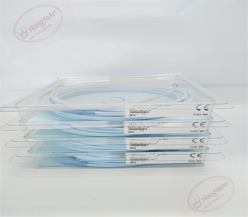
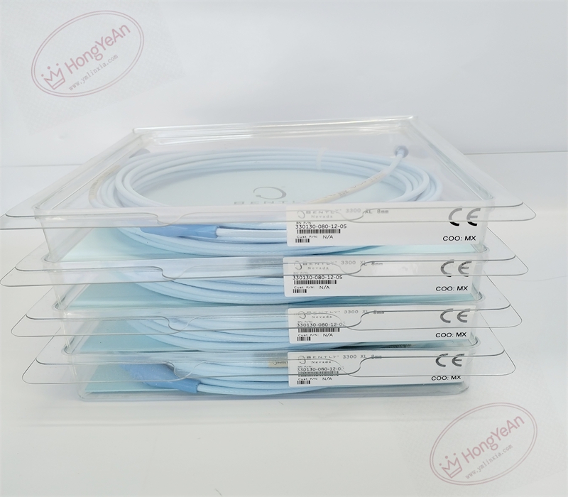
- Part Type: 3300‑XL FluidLoc tri‑axial extension cable, dual‑ended gold‑plated ClickLoc miniature coaxial connectors with molded connector protectors
- Cable Length: 8.0 meters (26.2 ft)
- Impedance: 75 Ω nominal; FEP insulation material; typical capacitance 69.9 pF/m
- Mechanical Construction: High‑temperature fluoropolymer outer jacket; non‑armored; FluidLoc barrier design blocks oil and process‑fluid wicking along cable inter‑layer; CableLoc reinforced connector‑to‑cable junction; integrated connector protective boots
- Environmental Ratings: Operating temperature −35 °C ~ +105 °C; storage −40 °C ~ +185 °C; relative humidity 5‑95 % non‑condensing
- Electrical Compatibility: Matches 3300‑XL 5 mm / 8 mm proximity probes and 3300‑XL proximitor sensors. Total transducer‑system length (probe integral cable + extension cable) must strictly match calibrated proximitor system length. Suffix‑05 denotes full international hazardous‑location agency approvals。
Core Functions
- Transmits high‑frequency eddy‑current sensor signal between proximity probe and proximitor sensor, maintaining signal integrity for gap‑voltage conversion, radial‑vibration and thrust‑position measurement. FluidLoc barrier stops oil and liquid from wicking through cable insulation layers, ideal for turbine compartments with heavy‑oil mist and fluid splashing. Extends physical reach of probe for routing to proximitor mounting location本特利。
- Deployed on steam‑turbines, gas‑turbines, centrifugal compressors and other critical rotating‑machinery as part of 3300‑XL transducer set, paired with 3500‑series / 1900‑series monitoring systems for machinery protection and condition‑diagnosis. Agency‑certified variant is qualified for installation within hazardous classified locations.
- Must maintain correct total system cable length; mismatched total length will shift sensitivity, degrade linear performance and produce erroneous gap‑voltage readings.
- The ClickLoc “click‑and‑turn” connector design provides repeatable, low‑contact‑resistance mating between transducer components; molded boots shield connector interfaces against contamination.
- Widely used in power‑generation, petrochemical and oil‑gas industrial sites. Distinguished ordering code:‑080‑ defines 8 m length,‑12‑ defines FluidLoc cable plus connector protectors,‑05‑ defines hazardous‑area approvals. Replacement requires re‑verification of total transducer‑system length and gap‑voltage calibration。
Installation Requirements
- Routing requirement: Route cable separate from high‑voltage power and large‑current motor cables to suppress electromagnetic interference. Avoid sharp bends, crushing, pinching and tensile pulling. Minimum cable bend radius 25.4 mm at all points along cable run.
- Connector handling: Mate ClickLoc connectors finger‑tight plus maximum 1/8‑turn; over‑torque will damage gold‑plated contact pins. Do not disassemble connector assemblies or remove protective boots.
- Grounding rule: Single‑point shield grounding implemented at proximitor‑sensor end only to eliminate ground‑loop noise.
- Environmental control: FluidLoc resists fluid wicking but is not submersible; avoid continuous direct liquid immersion at cable‑junction points. Outer‑jacket abrasion will cause signal drift or intermittent faults. For hazardous‑area deployment, strictly follow local installation codes for approved apparatus.
- Pre‑installation visual inspection: Inspect cable jacket for cuts, cracking or abrasion; inspect both‑end ClickLoc connector pins and protective boots for damage, corrosion or contamination before commissioning. After full transducer assembly, measure static gap voltage to verify valid linear‑range operation.
- Part‑number cross‑version distinction: 330130‑080‑12‑05 is non‑armored FluidLoc 8 m extension cable with hazardous‑area certifications. Standard‑cable, armored, non‑boot variants cannot be interchanged without re‑calculating total system length. Different‑length extension cables are not direct drop‑in substitutes; replacement demands full system‑length validation and gap‑voltage calibration。
Common Failure Modes
‑ Cable‑jacket abrasion, tri‑axial conductor micro‑fracture: intermittent gap‑voltage drift, noisy vibration readings, sporadic signal drop‑out. ‑ Improper bend radius or tensile pull stress: internal conductor damage, gradual signal degradation. ‑ ClickLoc connector pin contamination, corrosion or over‑torque damage: unstable signal connection, high‑frequency noise superimposed on vibration waveform. ‑ Multi‑point shield grounding: ground‑loop induced noise, unstable gap‑voltage output. ‑ Mismatched total transducer‑system length: incorrect sensitivity, offset gap‑voltage, invalid measurement data. ‑ Protective boot damage or removal: loss of FluidLoc fluid‑wicking protection, fluid ingress risk at connector interface.
-300x300.jpg)
Reviews
There are no reviews yet.