Description
Hardware Specifications
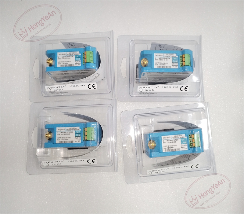
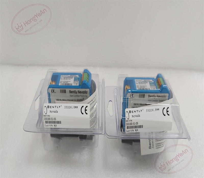
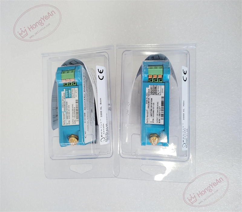
- Part Type: 3300‑XL proximitor sensor (pre‑amplifier), gold‑plated ClickLoc input connector, SpringLoc tool‑free output terminals
- Calibrated Total System Length: 5.0 meters (16.4 ft); mounting style: DIN‑rail mount, compatible with legacy 4‑hole panel‑mount footprint
- Sensitivity: 7.87 V/mm (200 mV/mil), tolerance ±5 %; linear measuring range 2.0 mm (80 mil)
- Power Supply: −17.5 Vdc ~ −26 Vdc, maximum operating current 12 mA
- Mechanical Construction: Die‑cast aluminum housing; electrically‑isolated mounting base; unit weight 246 g
- Environmental Ratings: Operating temperature ‑35 °C ~ +85 °C; storage ‑52 °C ~ +100 °C; relative humidity 5‑95 % non‑condensing
- Hazardous‑Area Certifications: Ex ia IIC, Ex nA IIC; Class I Div 1 Groups A‑D; IECEx / ATEX / CSA approvals, temperature code T5
- Electrical Compatibility: Works with 3300‑XL 5 mm / 8 mm proximity probes and matching 3300‑XL extension cables. Sum of probe integral cable plus extension cable must exactly match 5.0 m calibrated system length. Suffix‑05 denotes full international hazardous‑location agency approvals。
Core Functions
- Excites eddy‑current proximity probe, processes high‑frequency sensor signal and converts probe‑to‑shaft gap distance into stable DC gap‑voltage output for radial‑vibration, thrust‑position and shaft‑position measurement. DIN‑rail form factor optimised for high‑density cabinet installations in hazardous classified locations。
- Deployed on steam‑turbines, gas‑turbines, centrifugal compressors and other critical rotating‑machinery as core component of 3300‑XL transducer set; output signal feeds to 3500‑series / 1900‑series monitoring systems for machinery protection and condition‑diagnosis. Agency‑certified variant is qualified for installation within hazardous classified locations。
- High RFI/EMI immunity; can be installed inside fiberglass enclosures without extra metallic shielding, meets CE electromagnetic compatibility requirements。
- SpringLoc spring‑clamp terminals enable fast, tool‑less field wiring for power and signal connections。
- Widely used in power‑generation, petrochemical and oil‑gas industrial sites. Distinguished ordering code:‑51‑ defines 5 m calibrated total system length + DIN‑rail mounting,‑05‑ defines hazardous‑area approvals. Replacement requires strict matching of total transducer‑system length and gap‑voltage calibration verification。
Installation Requirements
- Mounting requirement: Primary installation via standard DIN‑rail; also fits legacy 4‑hole panel‑mount hole pattern. Mounting base provides electrical isolation; do not bypass internal isolation. Avoid locations with direct high‑temperature radiation or heavy‑fluid splashing onto housing. For hazardous‑area deployment, strictly follow local installation codes for approved apparatus。
- Transducer connection: Mate ClickLoc probe‑side connector finger‑tight plus maximum 1/8‑turn; over‑torque will damage gold‑plated contact pins. Do not disassemble ClickLoc connector assembly。
- Terminal wiring: Insert stripped wire into SpringLoc terminals and close spring clamp; ensure no loose wire strands. Strictly follow polarity for negative supply power, signal output and common return。
- Grounding rule: Transducer shield single‑point grounding strictly at proximitor‑sensor common terminal only; multi‑point shield grounding will induce ground‑loop noise。
- Environmental control: Housing is not submersible; protect unit against oil, water and process‑fluid spray. Ambient operating temperature must stay within‑35 °C ~ +85 °C range。
- Pre‑installation visual inspection: Inspect aluminum housing for deformation; inspect ClickLoc input connector pins for bending, corrosion or contamination; inspect SpringLoc terminals for damage before commissioning. After full transducer assembly, measure static gap‑voltage to confirm valid linear‑range operation。
- Part‑number cross‑version distinction: 330180‑51‑05 is 5 m calibrated DIN‑rail‑mount proximitor with hazardous‑area certifications. Panel‑mount (‑50‑xx), different‑system‑length, non‑approved or CN‑regional variants are not drop‑in substitutes. Replacement demands full system‑length validation and gap‑voltage calibration。
Common Failure Modes
‑ ClickLoc connector pin contamination, corrosion or over‑torque damage: unstable signal connection, high‑frequency noise superimposed on gap‑voltage output。 ‑ Mismatched total transducer‑system cable length: incorrect sensitivity, gap‑voltage offset, invalid measurement data。 ‑ Improper power supply voltage or reversed polarity: no output signal, permanent internal proximitor damage。 ‑ Multi‑point shield grounding: ground‑loop induced noise, unstable gap‑voltage drift。 ‑ SpringLoc terminal poor wire clamping: intermittent signal loss or fluctuating readings under vibration。 ‑ Excessive ambient temperature beyond specification: gradual sensitivity drift, premature unit failure。
Reviews
There are no reviews yet.