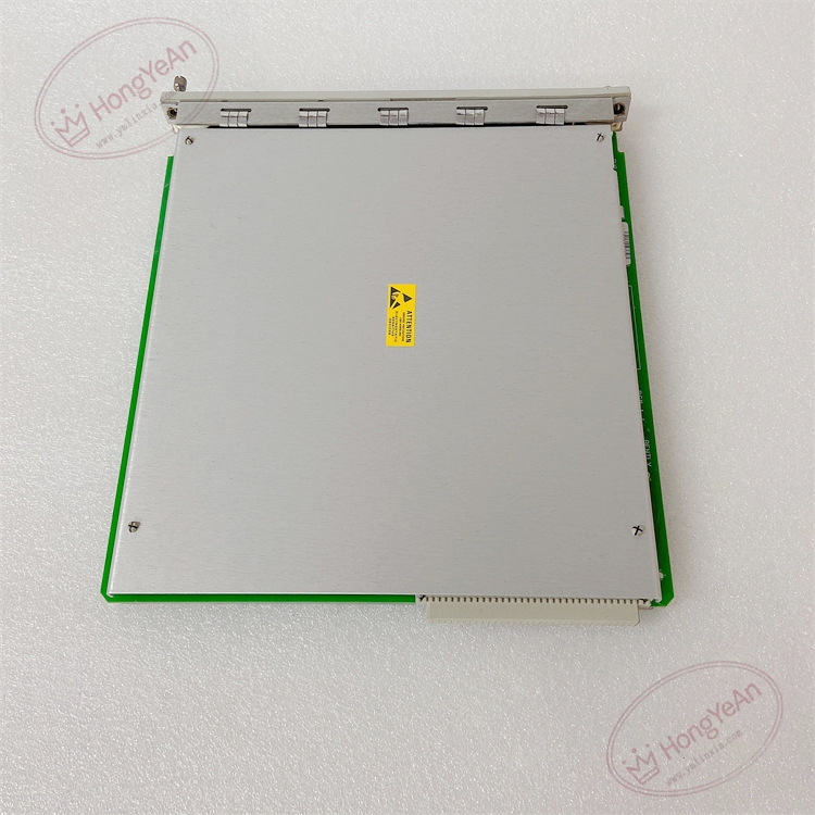
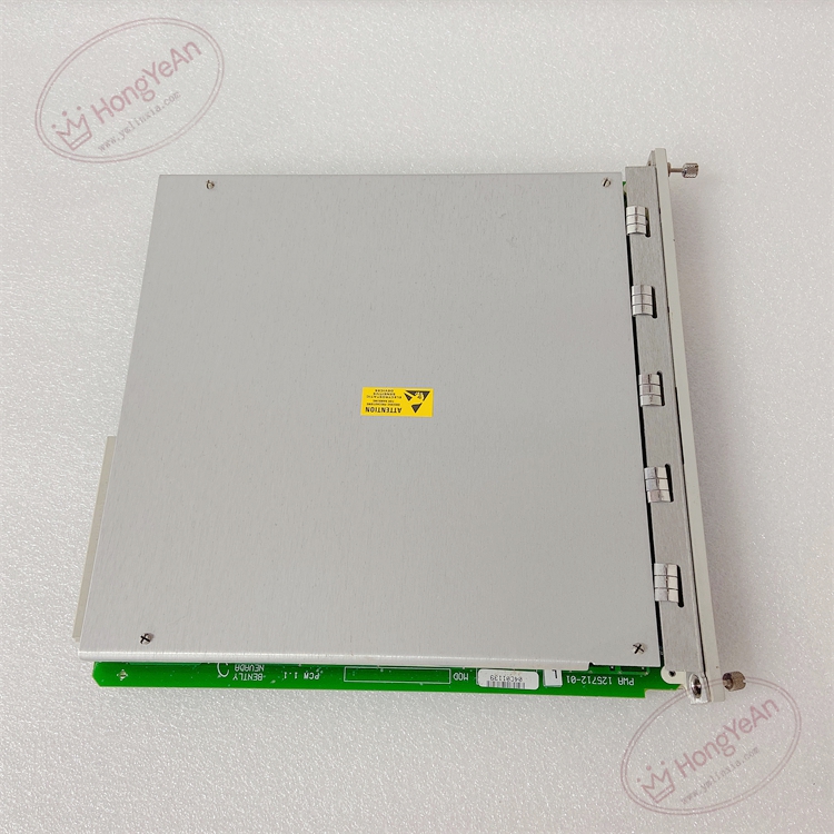
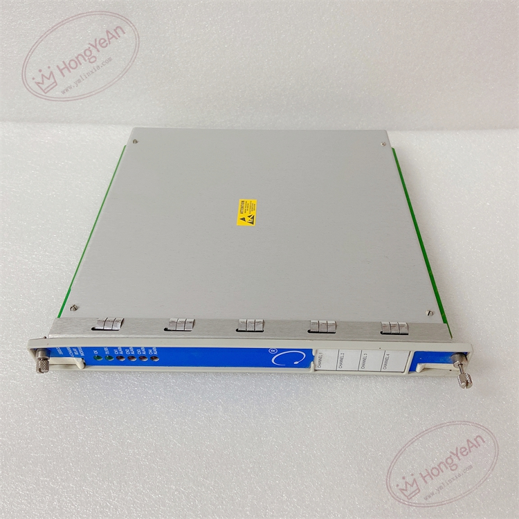
Description
Hardware & Electrical Specifications
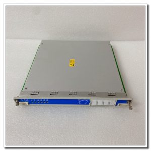
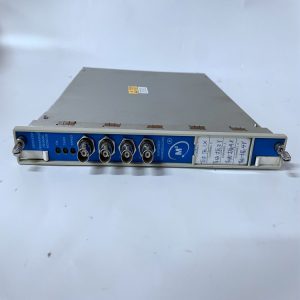
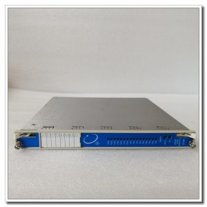
‑ Manufacturer: Bently Nevada (Baker Hughes) ‑ Compatible System: 3500‑05 full‑size / mini TSI machinery‑protection rack ‑ Functional Type: 4‑Channel Programmable Relay Output Module ‑ Channel quantity: 4 isolated SPDT (Form‑C) relay channels ‑ Relay Contact Rating: 5A @250VAC; 5A @30VDC ‑ Typical Response Time: ≤10 ms ‑ Typical Power Consumption: 10 W, powered by rack backplane bus ‑ Front‑panel Indicators: OK LED, four channel status LED for each relay output ‑ Matching Parts: Main board 125712‑01 must pair with rear I/O board 125720‑01, sold separately ‑ Hot‑swap: Supports hot‑swap; during replacement, measurement channels keep running, corresponding relay output is temporarily invalid. ‑ PCB Coating: Conformal coated for G3 harsh industrial cabinet environment
Environmental Specifications
‑ Operating Temperature: 0 °C ~ +60 °C ‑ Storage Temperature: ‑40 °C ~ +85 °C ‑ Relative Humidity: 5%‑95 % non‑condensing ‑ Vibration & Shock: Complies with API‑670 power‑plant cabinet EMC standards
Mechanical Data
‑ Dimension(W×H×D):25.4 mm ×120.7 mm ×251.5 mm ‑ Weight: approx 0.70 kg
Core Functions
- Configurable alarm‑drive logic: Each relay channel supports AND / OR voting logic; can select Alert, Danger, module fault status from any monitor channel inside rack as trigger sourceBaker Hugh….
- Relay mode selection: Each channel configurable for latching or non‑latching relay output.
- External interlock driving: Output dry‑contact signal to drive site alarm indicator, turbine/gas‑turbine protection trip interlock circuit.
- Multi‑module expansion: Multiple 3500/32 modules can be installed in one rack to expand relay output quantity.
- Self‑diagnosis: Module monitors internal working status, reports fault event to rack system log.
Installation, Replacement & Critical Warnings
- Module supports hot‑swap; measurement & protection logic of monitor cards keep running during hot‑swap, relay output will be temporarily disconnected.
- Compatibility warning: 125712‑01 main board must work with rear I/O board 125720‑01; cannot use without rear terminal board.
- After replacement, check OK and channel LED status; download rack configuration project, verify each relay action and voting‑logic function.
- Common failure mode: Relay contact burnout under over‑current load, backplane circuit surge damage. Avoid over‑rating load on relay contacts.
-
For TMR triple‑redundant protection system, trip logic needs multi‑relay voting configuration to realize fault‑tolerant protection.
Reviews
There are no reviews yet.