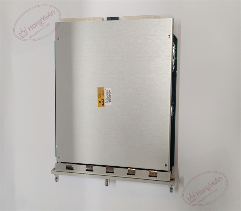
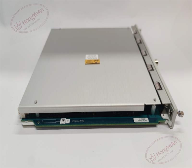
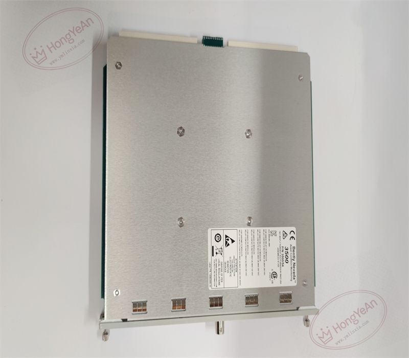
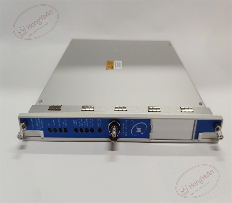
Description
Hardware & Electrical Specifications
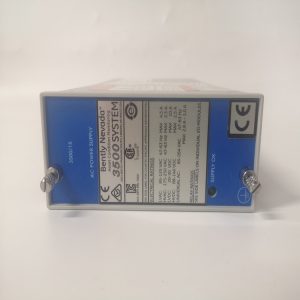
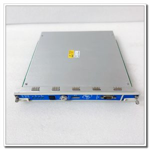
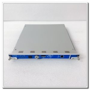
‑ Manufacturer: Bently Nevada (Baker Hughes) ‑ Compatible System: 3500‑05 full‑size / mini TSI rack, cooperates with 3500/22M TDI module, requires M‑series system firmware, redundant rack power supply is required for safety application ‑ Functional Type: 2‑Channel Upgraded Safety‑Grade Electronic Overspeed Detection Module ‑ Channel quantity: 2 independent pulse input channels ‑ Supported transducers: 3300XL proximity probes, magnetic pick‑up sensors ‑ Probe excitation power:‑24 VDC supplied by module ‑ Input signal range:+10 V ~ ‑24 V ‑ Input impedance:20 kΩ standard ‑ Measuring range: 1 ~ 99999 RPM ‑ Measurement accuracy:<100 RPM: ±0.1 RPM; 100‑10000 RPM: ±1 RPM; >10000 RPM: ±0.01 % reading ‑ Max input frequency:50 kHz ‑ Typical power consumption:8.0 W, powered by rack backplane bus ‑ Front‑panel Indicators: OK LED, TX/RX LED, Bypass LED, Test Mode LED, Alarm LED; short‑circuit‑protected BNC buffered signal output ‑ Matching Parts: Main‑board 286566‑01 must pair with rear I/O board 286574‑01, sold separately ‑ Hot‑swap: Electrically supports hot‑swap; for safety overspeed rack, power‑off corresponding slot before plug‑pull module on running unit to avoid protection‑loss risk. ‑ PCB Coating: Conformal coated for G3 harsh industrial cabinet environment ‑ Safety Certification: SIL‑2 capable within complete certified 3500 overspeed voting system set; ATEX / UL hazardous‑area approvals available.
Environmental Specifications
‑ Operating Temperature:‑30 °C ~ +65 °C ‑ Storage Temperature:‑40 °C ~ +85 °C ‑ Relative Humidity:5%‑95 % non‑condensing ‑ Vibration & Shock: Complies with API‑670 power‑plant cabinet EMC standards
Mechanical Data
‑ Dimension(W×H×D):241.3 mm ×24.4 mm ×241.8 mm ‑ Weight: approx 0.84 kg
Core Functions
- Pulse‑signal conditioning: Supply‑24 VDC for proximity probes; condition magnetic pick‑up pulse signals for overspeed acquisition.
- High‑safety overspeed detection: Fast‑response overspeed trip logic, supports multi‑module 2‑out‑of‑2 / 2‑out‑of‑3 voting architecture to improve system safety and reduce false‑trip probability.
- Flexible parameter configuration: Events‑per‑turn, overspeed trip setpoint, pre‑overspeed alarm setpoint, trip hold‑off delay configurable; stores peak speed value.
- Hardware trip & alarm output: Overspeed condition triggers hardware relay trip output; pre‑overspeed alarm generates rack system events.
- Analog output: Each channel provides isolated 4‑20 mA output via rear I/O board for DCS speed display and data acquisition.
- Buffered BNC output: Front‑panel BNC copies raw transducer signal for portable field diagnostic instrument connection.
- Self‑diagnosis: Continuous transducer cable fault detection, report module hardware fault to rack system log.
Installation, Replacement & Critical Warnings
- Electrical hot‑swap is supported; for safety‑related overspeed rack, power‑off corresponding slot before insert / remove module to avoid protection‑loss risk.
- Compatibility warning: ‑ Cannot drop‑in replace legacy 3500/53‑133388‑01 overspeed module; must use matched rear‑I/O board 286574‑01, rack firmware version ≥5.40 is required. ‑ For safety overspeed application, adopt 2‑out‑of‑3 voting system with three identical 286566‑01 modules and rack redundant power supply, strictly follow API‑670 requirement. ‑ Magnetic pick‑up sensors perform poorly under low‑speed condition; proximity probes are preferred for overspeed protection input.
- After replacement, check OK / Bypass / Test‑Mode LED status; download rack configuration project, complete overspeed simulation trip test, verify speed reading, trip threshold and 4‑20 mA output function.
-
Common failure mode:‑24 VDC transducer power circuit damage, input‑circuit surge damage, component aging; transducer cable short‑circuit may burn front‑end conditioning circuit.
Reviews
There are no reviews yet.