.jpg "本特利-350015-(1)")
.jpg "本特利-350015-(2)")
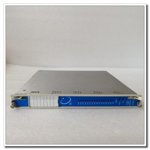
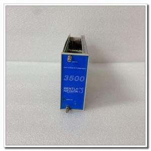
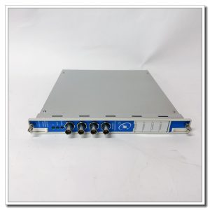
Description
Detailed Technical Parameters
- Input selection: Multiple variants available, including low‑voltage AC 85‑132VAC, high‑voltage AC 175‑264VAC, universal AC 85‑264VAC, low‑voltage DC 20‑30VDC and high‑voltage DC 88‑150VDC, matching different site power‑supply conditions本特利.
- Total rated output power: 180‑250W depending on variant. Internal multi‑rail DC outputs supply +5V, +3.3V, +12V for backplane bus.
- Built‑in protection mechanisms: over‑voltage, under‑voltage, over‑current, short‑circuit and over‑temperature shutdown protection.
- Status indication: “Supply OK” green LED on front panel, providing real‑time power‑running status. Fault information will be uploaded to 3500 system event log via frame manager 3500/20.
- Installation requirement: Occupies dedicated two half‑slots on far‑left side of 3500 rack; supports hot‑swap replacement without shutting down the whole rack when redundant power is configured.
- Ambient specification: Operating temperature‑30℃ ~ +65℃; storage‑40℃ ~ +85℃; humidity 5‑95% non‑condensing, IP20 cabinet‑installation.
- Compatibility note: Must match original 3500 series rack backplane. Mixed‑use of different input‑type power variants in redundant group is not allowed. After replacement, verify power‑supply variant setting inside 3500 configuration software.
.jpg)
Mechanical & Structural Features
Consists of front power main‑board and rear PIM input interface module. Rear PIM module defines actual input mode (AC or DC). Gold‑plated backplane connectors deliver stable multi‑channel DC power to each slot. The whole assembly adopts conformal‑coated PCB, resisting dust, slight corrosive gas and moisture inside power‑plant cabinets. Metal housing provides mechanical shielding against electromagnetic interference.
Real‑world Application Background
Installed inside turbine machinery‑protection cabinets. It supplies stable power for vibration monitor modules, speed monitor boards, relay output cards and communication interfaces. For critical rotating‑machinery protection loops, dual‑redundant 3500/15 power units are generally adopted. If one power unit fails, the backup unit automatically takes over the full load, avoiding protection‑system outage caused by single‑point power fault.
When single power module is damaged under redundant configuration, system will generate power‑channel fault alarm, while the whole protection system can keep normal operation. If only one power unit is deployed, power‑supply failure will make all monitoring and protection functions invalid.
Field Installation & Commissioning Points
- For redundant configuration, two power modules should be fed from two independent power‑supply loops to eliminate single‑source failure risk.
- Strictly perform ESD anti‑static protection during replacement. Under redundant mode, hot‑swap can be performed online; cut off input power if single‑power configuration.
- Tighten rear‑side PIM wiring terminals to prevent loose contacts leading to intermittent power drop.
- After hardware replacement, observe “Supply OK” LED status, check rack backplane bus voltage, view system event log to confirm no power‑supply related alarms.
- On‑site component‑level repair is prohibited. Replace the complete power‑supply assembly when permanent hardware damage occurs.
Typical On‑site Fault Phenomena & Analysis
- Supply‑OK LED goes out, whole rack no power output: Check external input power, fuses and PIM terminal wiring; confirm whether input voltage is within rated range.
- Random rack reboot or module dropout: Focus on cabinet heat‑dissipation condition, aging internal capacitor risk of old power unit, and poor backplane contact.
- Redundancy switchover failure after one power unit fault: Verify two power units are same variant, check load‑sharing circuit and power‑input loop independence.
- Intermittent power‑supply channel fault alarm: Check cabinet temperature, dust accumulation and terminal oxidation; eliminate power‑grid surge and interference.
Reviews
There are no reviews yet.