.jpg "本特利-9200-06-01-10-00-(1)")
.jpg "本特利-9200-06-01-10-00-(2)")
Description
Core technical parameters
- Sensitivity: 20 mV/mm/s (500 mV/in/s), tolerance ±5 % @100 Hz under 10 kΩ load condition.
- Frequency response: 4.5 Hz ~ 1000 Hz (+0 /‑3 dB). Max measurable displacement 2.54 mm peak‑to‑peak.
- Coil resistance:1250 Ω ±5 %, coil inductance 125 mH typical value.
- Shock resistance: 50 g peak acceleration on non‑sensitive axis. Max transverse sensitivity ±10 %.
- Working ambient:‑29 ℃ ~ +121 ℃; storage‑40 ℃ ~ +85 ℃, humidity 5‑95 % non‑condensing.
- Compatibility note: Matches 3500/45 or other vibration monitor modules. Needs dedicated shielded sensor cable. Signal polarity must be checked during installation; wrong wiring will result in reversed vibration reading.
Physical features
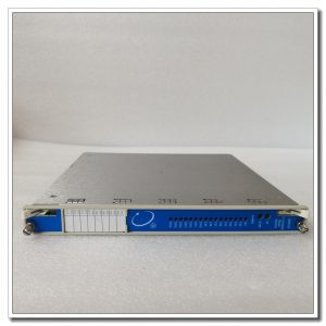
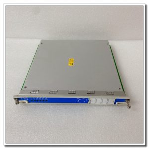
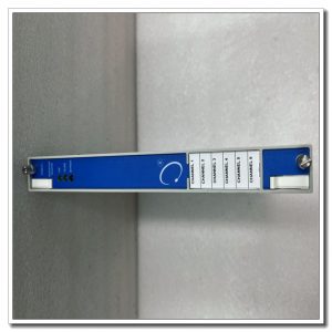
Compact stainless‑steel housing for field equipment surface mounting. Two‑pin terminal connector for signal cable connection. Serial number and specification information are marked on housing label. Internal moving‑coil assembly, PCB protected by conformal coating against industrial cabinet dust and moisture.
Practical field notes
Installed directly on bearing housing or equipment casing of steam‑turbine, gas‑turbine and large‑size fan units. Captures absolute casing vibration velocity for machinery condition‑monitoring system. Sensor damage or cable breakage will lead to zero vibration reading and trigger system alarm. During replacement, strictly follow ESD anti‑static rules. Fasten mounting thread, keep sensor sensing axis aligned with measuring direction. After installation, inspect coil resistance with multimeter, verify vibration value reading on monitoring system, clear alarm log before putting into service.
Installation reminders
Do not apply excessive torque during sensor mounting, avoid internal coil mechanical damage. Sensor signal cable uses shielded twisted‑pair, separate from high‑power cables to reduce electromagnetic interference. Avoid sharp bending of signal wiring. Record coil resistance baseline value at commissioning for later fault comparison. On‑site internal coil repair is forbidden; replace whole sensor assembly when permanent failure occurs.
Typical on‑site fault phenomena
- Vibration reading zero: Check cable breakage, connector loose contact, measure coil resistance for open‑circuit condition.
- Vibration value obvious deviation: Confirm installation orientation, check mounting base looseness risk.
- Unstable fluctuating reading: Inspect cable shielding grounding, connector oxidation and mechanical vibration interference.
- Abnormal low coil resistance: Judge internal coil short‑circuit failure risk.
.jpg)
Reviews
There are no reviews yet.