Description
Hardware & Electrical Specifications
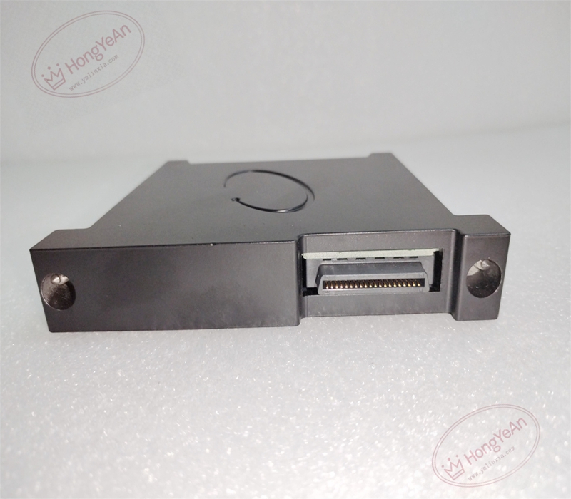
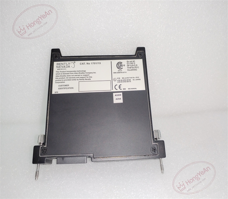
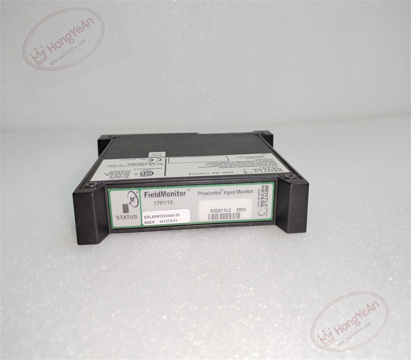
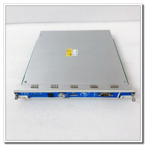
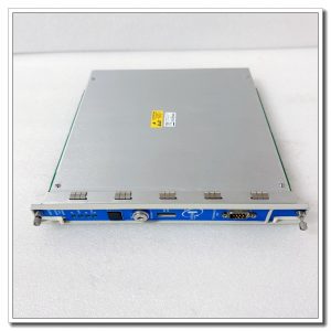
‑ Manufacturer: Bently Nevada (Baker Hughes) ‑ Compatible System: FieldMonitor 1701 machinery monitoring system ‑ Functional Type: Dual‑Channel Proximitor Input Monitor ‑ Inputs: 2‑channel eddy‑current proximity probe inputs (3300‑XL / 3300 series probes) ‑ Measurable Parameters: Shaft radial vibration (peak‑to‑peak), thrust axial position, average gap position ‑ Measurement Range: Configurable according to matched probe‑cable assembly ‑ Alarm Setting: Alert and Danger thresholds per channel; delay time 0.15‑20 s, latching / non‑latching selectable ‑ Analog Output: 2 × 4‑20 mA isolated outputs for DCS/PLC trending ‑ Diagnostics: Probe open‑circuit, short‑circuit, cable fault and module self‑diagnosis, NOT‑OK status ‑ Test Interface: Buffered raw gap‑voltage BNC test ports per channel for on‑site troubleshooting ‑ Relay Output: Form‑C alarm relay contacts for Alert, Danger and module fault ‑ Backplane Power: 24 VDC supplied from 1701‑10 power supply module via baseplate ‑ Indicators: Front‑panel LED array for channel status, alarm and NOT‑OK fault indication ‑ Connectors: Edge‑card backplane connector; coaxial probe input connectors ‑ Mounting: Plug‑in slot installation on 1701/05 or 1701/06 terminal base ‑ PCB Finish: Conformal coated for harsh power‑plant cabinet environment ‑ Hot‑swap: Non‑hot‑swappable, de‑energize rack DC power for module replacement
Environmental Specifications
‑ Operating Temperature: ‑30 °C ~ +70 °C ‑ Storage Temperature: ‑40 °C ~ +85 °C ‑ Relative Humidity: 5%‑95 % non‑condensing ‑ Vibration & Shock: Complies with rotating‑machinery cabinet EMI and transient requirements
Mechanical Data
‑ Weight: approx 0.31 kg
Core Functions
- Proximity‑probe signal conditioning: Processes two‑channel eddy‑current probe signals, computes shaft radial vibration and thrust axial displacement values.
- Configurable alarm supervision: Compares measured values against Alert / Danger set‑points; adjustable time‑delay suppresses nuisance alarms during machine start‑up.
- Transducer fault diagnostics: Continuously monitors probe and cable health; triggers NOT‑OK status upon open‑circuit / short‑circuit faults.
- Analog and relay alarm output: 4‑20 mA signals transmit measurement data to plant DCS; relay contacts output fault status to local annunciator.
- Field‑service test point: Buffered BNC ports output raw gap‑voltage waveform for oscilloscope on‑site calibration and troubleshooting.
Installation, Replacement & Critical Warnings
- De‑energize 1701 rack 24 VDC power before removing module; non‑hot‑swappable.
- Must use matching total‑length probe‑extension‑cable assembly; mismatched cable length causes severe measurement drift.
- Adjust probe target gap to mechanical mid‑gap position during commissioning; verify gap‑voltage via BNC buffered output.
- After installation, configure measurement range and alarm thresholds; validate 4‑20 mA output and relay‑alarm function.
- Common failure mode: Coaxial probe‑cable damage, surge damage to input conditioning circuits. Inspect probe installation and cabling when NOT‑OK alarms activate.
-300x300.jpg)
Reviews
There are no reviews yet.