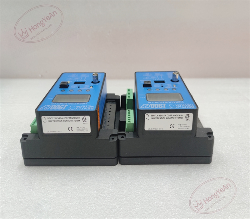
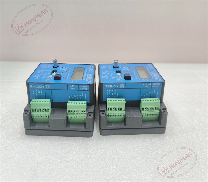
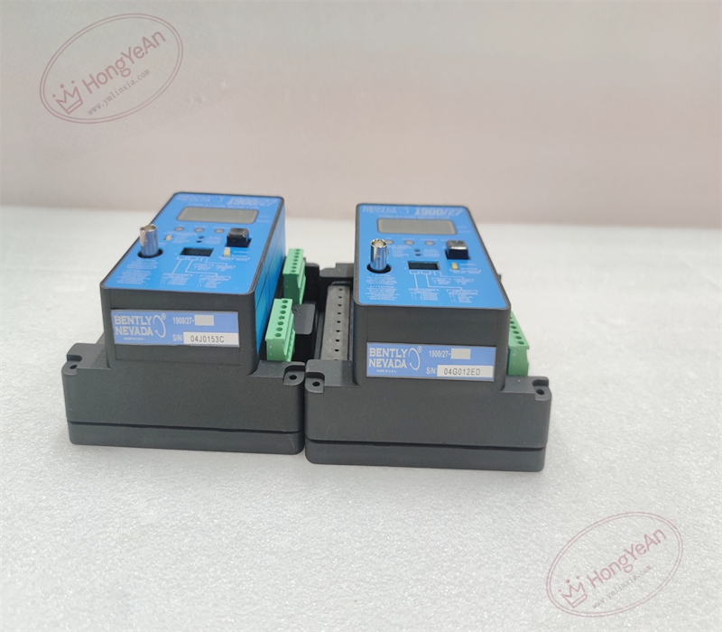
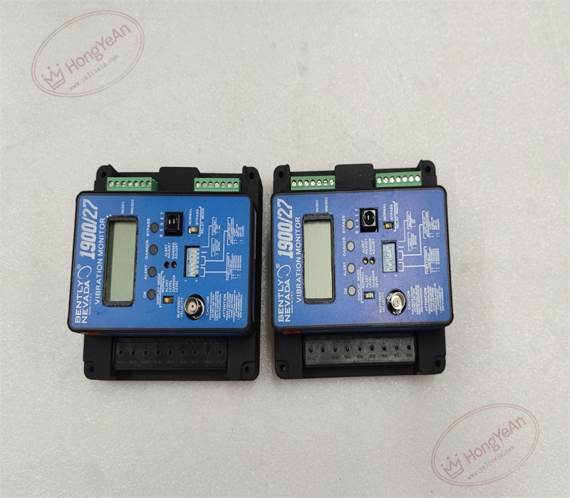
Description
Hardware & Electrical Specifications
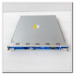
‑ Manufacturer: Bently Nevada (Baker Hughes) ‑ Functional Type: Single‑Channel Seismic Vibration Monitor ‑ Sensor Input: For 100 mV/g accelerometer (200150 / 190520 series) ‑ Measurement: Peak velocity, configurable full‑scale range ‑ Frequency Response: 8 Hz ~ 4000 Hz (‑3 dB) ‑ Power Supply Options: • Low‑DC version: 18‑36 VDC • Universal AC/DC version: 85‑264 VAC / 110‑370 VDCManualsLib ‑ Analog Output: Isolated 4‑20 mA proportional to vibration value ‑ Relay Output: 2 × SPDT relay contacts (Alert, Danger), rating 6 A @28 VDC / 300 VAC ‑ Diagnostics: Transducer fault detection, built‑in self‑test routine ‑ Indicators: Front‑panel LCD numerical display; OK, Alert, Danger, Fault LED indicators ‑ Test Interface: BNC buffered transducer output for raw vibration waveform measurement ‑ Connectors: Accelerometer input connector; screw terminals for power, 4‑20 mA and relay circuits ‑ Mounting: Cabinet front‑panel cut‑out installation ‑ Certification: CSA / FM Class I Div 2 hazardous‑location approval ‑ Hot‑swap: Non‑hot‑swappable; de‑energize power before replacement
Environmental Specifications
‑ Operating Temperature: ‑20 °C ~ +60 °C ‑ Storage Temperature: ‑40 °C ~ +85 °C ‑ Relative Humidity: 5%‑95 % non‑condensing ‑ Vibration & Shock: Complies with rotating‑machinery cabinet EMI and transient requirements
Mechanical Data
‑ Dimensions (W × H × D): 132 mm × 132 mm ×71 mm ‑ Weight: approx 0.40 kg
Core Functions
- Bearing‑housing vibration monitoring: Processes accelerometer signal, calculates peak velocity vibration for pump, fan, motor bearing‑housing condition evaluation.
- Two‑level alarm protection: Configurable Alert and Danger thresholds with adjustable time‑delay; latching / non‑latching relay mode selectable.
- Process‑system interface: 4‑20 mA analog output sends vibration trending value to plant DCS / PLC system.
- Local indication & troubleshooting: On‑site LCD readout; BNC buffered output allows waveform capture by portable oscilloscope during commissioning and troubleshooting.
- Self‑diagnostic & self‑test: Transducer fault detection; manual self‑test function to verify monitor hardware and relay‑output operation.
Installation, Replacement & Critical Warnings
- De‑energize monitor power supply before replacement; unit is non‑hot‑swappable. Isolate accelerometer wiring during terminal maintenance.
- Confirm accelerometer sensitivity parameter matches hardware setting; mismatched sensitivity produces large measurement error.
- Set full‑scale range, Alert / Danger thresholds and time‑delay according to machinery OEM specification.
- After installation, perform self‑test routine; verify LCD reading, 4‑20 mA output and relay‑alarm action.
-
Common failure mode: Surge damage to accelerometer input circuit; accelerometer cable damage. Investigate field sensor and cabling when transducer‑fault alarms occur.
-300x300.jpg)
Reviews
There are no reviews yet.