Description
Hardware & Electrical Specifications
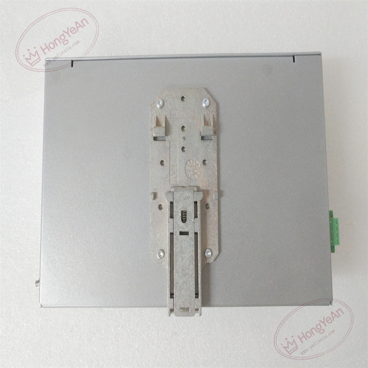
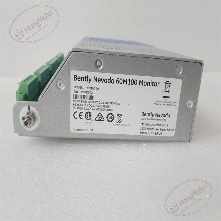
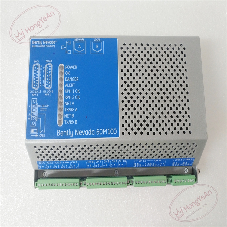
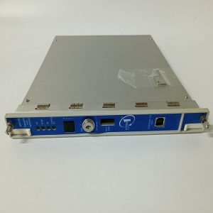
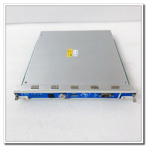
‑ Manufacturer: Bently Nevada (Baker Hughes) ‑ Functional Type: Machinery Condition‑Monitoring Monitor ‑ Input Channels: Multi‑channel vibration / acceleration inputs, tachometer speed input ‑ Signal Type: Accelerometer, proximity transducer, pulse‑type tachometer ‑ Auxiliary Power: 24 VDC nominal power input ‑ Communication Interfaces: Dual RJ45 Ethernet (Modbus‑TCP), RS232 serial port ‑ I/O: Analog output channels; discrete alarm relay outputs for status and fault signalling ‑ Data Storage: On‑board event buffer stores alarm timestamps and waveform snapshot data ‑ Indicators: Front‑panel multi‑LED for power, network link, module fault and channel alarm status ‑ Connectors: Removable screw terminal blocks for field sensors, power and I/O signals; RJ45, DB9 serial connector ‑ Mounting: Cabinet DIN‑rail mounting ‑ Enclosure: Perforated metal housing, IP20 ‑ PCB Finish: Conformal coated for harsh industrial cabinet environments ‑ Hot‑swap: Non‑hot‑swappable; power must be de‑energized for module replacement
Environmental Specifications
‑ Operating Temperature: ‑20 °C ~ +60 °C ‑ Storage Temperature: ‑40 °C ~ +85 °C ‑ Relative Humidity: 5%‑95 % non‑condensing ‑ Vibration & Shock: Complies with wind‑turbine and power‑plant cabinet EMI and transient requirements
Mechanical Data
‑ Weight: approx 2.9 kg
Core Functions
- Multi‑sensor signal acquisition: Collects vibration, acceleration and shaft‑speed signals from field transducers for rotating‑machinery condition evaluation.
- Condition‑monitoring calculation: Executes vibration‑analysis algorithms, computes bearing and gearbox health indices, compares measurements against configurable alarm thresholds.
- Alarm & event capture: Generates level‑1 / level‑2 alarm outputs; captures fault timestamps and waveform snapshots for post‑failure root‑cause analysis.
- Supervisory system interface: Modbus‑TCP uploads real‑time measurement values and alarm status to plant DCS / SCADA system.
- Local discrete & analog outputs: Relay alarm contacts and analog output signals for local annunciator and auxiliary equipment.
Installation, Replacement & Critical Warnings
- De‑energize 24 VDC auxiliary power before replacement. Unit is non‑hot‑swappable. Field transducer wiring should be isolated during terminal maintenance work.
- After hardware replacement, download matching project configuration and firmware via dedicated 60M‑Series configuration software; factory default settings cannot be used for site operation.
- Torque all screw‑terminal connections properly; loose terminals cause intermittent sensor signal dropout and false‑alarm triggers.
- After power‑on, verify front‑panel LED status, check sensor signal quality, validate alarm thresholds and Modbus‑TCP data interaction with host system.
-
Common failure mode: Field‑wiring surge damage to sensor input circuits, Ethernet transceiver damage. Inspect transducer cabling when missing‑sensor or abnormal‑vibration alarms appear.
-300x300.jpg)
Reviews
There are no reviews yet.