Description
Core performance features
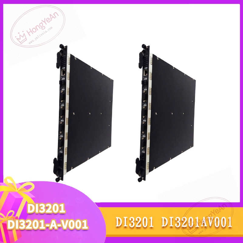
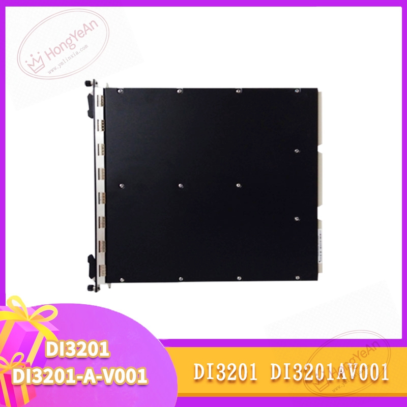
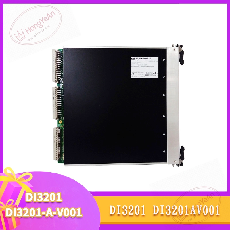
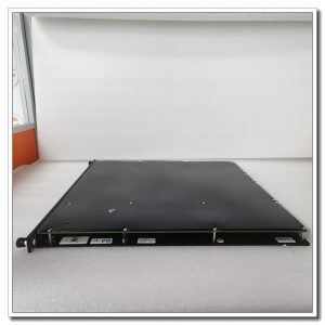
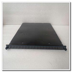
Mechanically designed for vertical insertion into HIMax system rack, power and system bus communication are realized via backplane golden‑finger contacts. Triple‑modular redundant processing circuit runs three independent signal channels simultaneously; single‑channel hardware fault will not lead to loss of safety function, achieving high fault‑tolerance capability. Total 32 galvanically isolated digital input channels, supporting dry‑contact and 24 VDC active signal. Rated input voltage range 18‑30 VDC, typical input current ≤5 mA per channel. Signal high‑level threshold 15‑30 VDC, low‑level threshold ‑3‑+5 VDC. Hardware response time ≤5 ms, input filter debounce time configurable via engineering software from 1 ms to 100 ms. Complete per‑channel diagnostic function can detect open‑circuit, short‑circuit to ground, short‑circuit to power supply and signal over‑range. Diagnostic coverage ≥99.5 %. On‑board non‑volatile memory stores historical fault events with time stamps for later troubleshooting. Front‑panel multi‑LED indicator array reflects module power‑on status, bus communication status, individual channel alarm and global module hardware failure status. Equipped with rotary locking latch for secure rack mounting. Hot‑swap is supported under redundant system configuration; maintenance personnel can swap module while the safety system keeps running, all field cables remain connected on external termination base board without modification. Communicates with safety CPU through dedicated internal X‑Bus safety bus, realizes deterministic real‑time data transmission between I/O module and main processor. Safety certification: SIL3 according to IEC 61508, PL e / Cat.4 according to EN ISO 13849‑1, with TÜV, UL, CE approvals. Environmental parameters: operating ambient temperature 0‑60 ℃, storage temperature ‑40‑+85 ℃, IP20 protection degree, only for installation inside industrial control cabinet. Module weight approx. 1 kg‑1.25 kg.
On‑site application scenarios
Primarily used in SIS safety instrument cabinets for petrochemical plants, refineries and thermal power stations. Responsible for collecting feedback signals of safety‑related field devices: emergency‑stop buttons, safety gate switches, pressure / temperature safety switches, valve position feedback contacts, fire‑gas detection contact signals. These input data serve safety interlock logic judgment for ESD emergency shutdown and F&G fire‑gas protection systems. If this module fails, safety‑related signal acquisition will be interrupted and may trigger safety system trip. It acts as vital maintenance spare part for existing HIMax safety automation projects. After spare‑part replacement, no revision of safety application logic program is required. Operators only need to verify bus communication status, check each channel signal reading and perform signal simulation test before restoring the system to online operation.
Installation & operating notes
Hot‑swap function is available, but repeated frequent plug‑pull during system runtime shall be avoided to prevent abrasion and oxidation of backplane golden‑finger contacts. For non‑redundant system configuration, cut off rack power supply before module removal and insertion. Field digital‑input signal cables must adopt shielded twisted‑pair cables. Signal wiring shall be physically separated from high‑power power cables to reduce electromagnetic interference. Improper grounding will cause signal jumping and false alarms. Before hardware replacement, back‑up complete safety project configuration files. After installing new module, confirm that module firmware version is consistent with the whole HIMax system. Version mismatch will cause internal bus communication failure or partial‑function abnormality. Maintain good cabinet ventilation and dust‑proof environment. Dust accumulation and excessive operating temperature are common causes of intermittent channel faults. When permanent hardware damage occurs, replace the whole complete module. Component‑level repair on‑site is prohibited, which will invalidate safety certification.
Common field phenomena & disposal thoughts
- All module front‑panel indicators stay dark after rack power‑on: Inspect rack back‑plane power supply condition. Re‑seat module firmly in slot. If input power is normal and indicators still remain off, internal hardware damage is confirmed.
- Individual channel reading fixed / no signal change: Check field loop for open‑circuit, short‑circuit or contact damage. Verify signal‑range configuration in engineering software. Swap channel assignment for comparison test. If external wiring and field device are normal, internal channel circuit is suspected damaged.
- Random signal fluctuation on channels: Check shielding grounding quality of signal cables. Eliminate nearby strong interference sources. Inspect rack mechanical vibration whether it results in poor contact of back‑plane golden fingers.
- I/O station reports module offline alarm: Re‑install and lock module. Check back‑slot condition for dust and oxidation. Verify firmware revision compatibility between DI3201‑DI3201‑A‑V001 and main safety CPU.
- Module reports persistent channel diagnostic alarm: Confirm field sensor and loop status. Check whether input signal exceeds module rated range. If external side is fault‑free, internal channel failure occurs.
-300x300.jpg)
Reviews
There are no reviews yet.