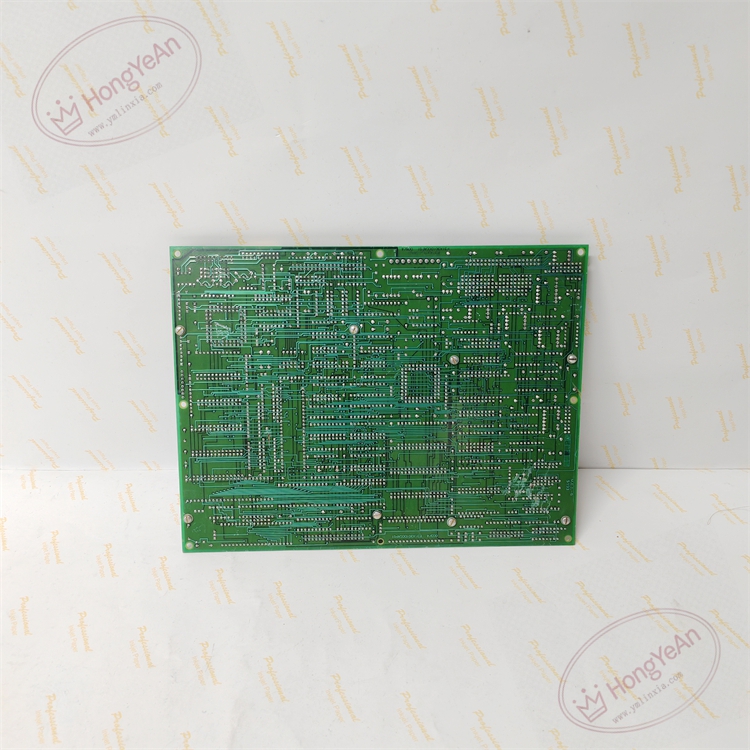
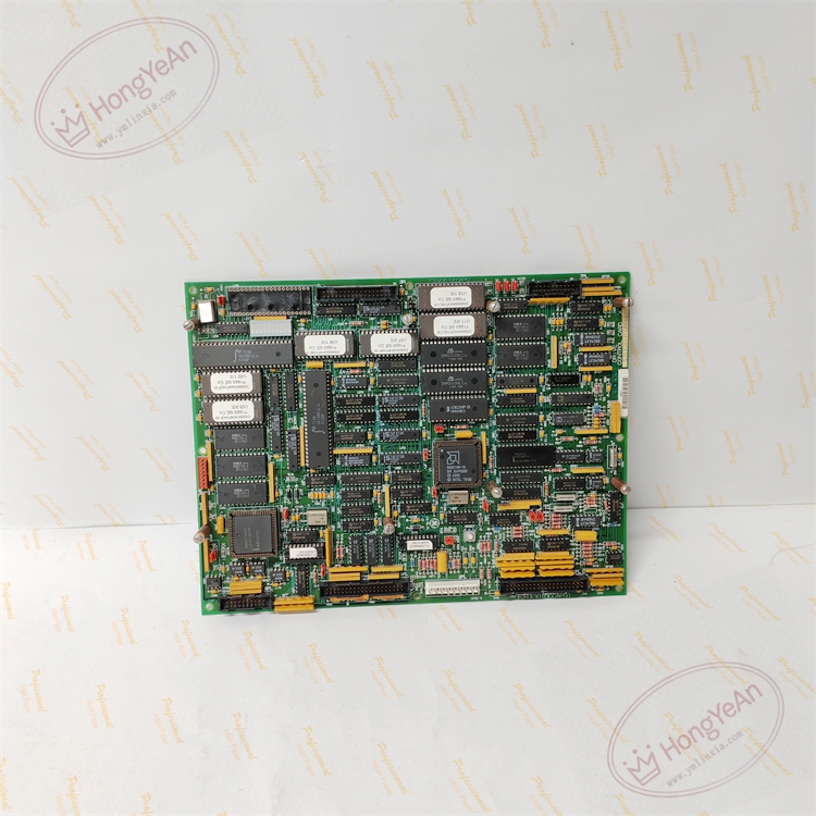
Description
Hardware & Electrical Specifications
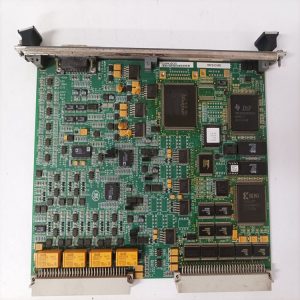
‑ Manufacturer: GE General Electric ‑ Compatible System: Speedtronic Mark‑V, DC‑300 drive platform ‑ Functional Acronym: DCCA (Drive Control Board) ‑ Main Processor: Intel 80186 microprocessor ‑ Signal Types Handled: • Encoder / analog feedback inputs for speed and torque measurement • Drive command outputs to power stage • Backplane communication, alarm and event‑log signals ‑ Connectors: Multi‑pin ribbon headers for feedback sensors, power stage and rack backplane ‑ On‑Board Jumpers: Configurable jumpers for drive‑loop parameters and hardware address setup. All jumper positions must be exactly duplicated during replacement ‑ Controls: On‑board reset push‑button ‑ Indicators: LED array for power, processor activity and drive‑fault diagnosis ‑ Power Source: +5 VDC, ±15 VDC supplied from drive‑rack backplane ‑ PCB Finish: Conformal coated multilayer PCB ‑ Compatibility Restriction: For Mark‑V / DC‑300; not compatible with Mark‑VI / Mark‑VIe racks. G2 firmware version must match site drive‑system configuration.
Environmental Specifications
‑ Operating Temperature: 0 °C ~ +60 °C ‑ Storage Temperature: −40 °C ~ +85 °C ‑ Relative Humidity: 5%‑95 % non‑condensing ‑ Installation Environment: Drive‑control cabinet interior, Pollution Degree 2 ‑ EMC: Designed for power‑plant cabinet EMI and switching‑transient conditions
Mechanical Data
‑ Physical Dimension: approx 305 mm × 205 mm ‑ Mounting: Standard slot installation inside Mark‑V / DC‑300 drive rack ‑ Weight: approx 1.0 kg
Core Functions
- Closed‑loop drive regulation: Executes speed, torque and current control algorithms for turbine auxiliary motor drives.
- Feedback signal processing: Acquires encoder and analog feedback to calculate real‑time motor operating values.
- Power‑stage command generation: Generates control outputs to power converter modules to regulate motor performance.
- Event & alarm logging: High‑resolution recording of trip‑history, fault codes and operating events for post‑fault analysis.
- On‑board diagnostics: Reset button and LED indicators support commissioning and troubleshooting drive‑related faults.
Installation, Replacement & Critical Warnings
- Complete system power‑down and lock‑out procedure required before servicing. Non‑hot‑swappable. ESD wrist‑strap protection is mandatory for PCB handling.
- Record all original jumper positions and confirm G2 firmware revision prior to removal. Wrong jumpers or firmware mismatch may cause motor runaway or drive trips.
- Secure ribbon‑cable and backplane connectors firmly; poor contact leads to intermittent feedback loss and random drive faults.
- After power‑on, perform full drive‑loop verification: check LED status, validate speed feedback, test motor operation and confirm event‑log function.
-
Common failure mode: Surge from motor‑side wiring may damage feedback input circuits. Inspect field wiring when speed anomalies occur.
Reviews
There are no reviews yet.