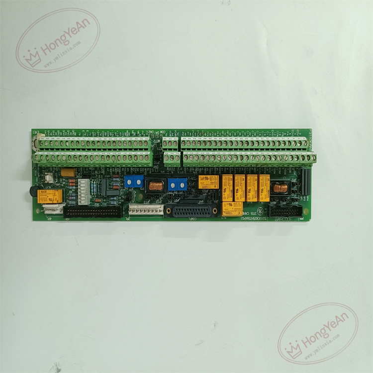
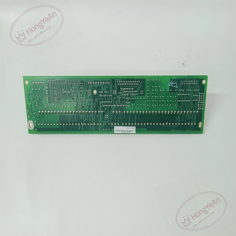
Description
Hardware & Electrical Specifications
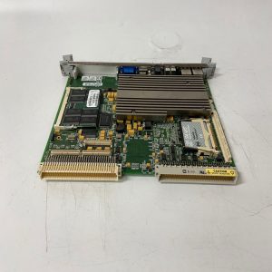
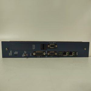
‑ Manufacturer: GE General Electric ‑ Compatible System: DC‑300 drive, EX2000 excitation system ‑ Functional Acronym: NTBAP (Terminal Board) ‑ Signal Types Handled: • Differential A‑Quad‑B encoder, tachometer pulse inputs • Analog field signals, discrete digital inputs • Multi‑channel form‑A / form‑C relay alarm outputs ‑ Encoder Power: Jumper selectable +5 VDC / +15 VDC ‑ Connectors: Screw field terminal blocks, multi‑pin ribbon headers for connection to control rack ‑ On‑Board Jumpers: Encoder supply voltage selection. All jumper positions must be exactly duplicated during replacement ‑ Adjustment: On‑board potentiometers for analog signal scaling calibration ‑ Indicators: LED array for channel status and fault diagnosis ‑ PCB Finish: Conformal coated multilayer PCB ‑ Compatibility Restriction: Designed for DC‑300 / EX2000; not compatible with Mark‑VI / Mark‑VIe racks. G1 is hardware revision.
Environmental Specifications
‑ Operating Temperature: 0 °C ~ +60 °C ‑ Storage Temperature: −40 °C ~ +85 °C ‑ Relative Humidity: 5%‑95 % non‑condensing ‑ Installation Environment: Drive‑excitation cabinet interior, Pollution Degree 2 ‑ EMC: Designed for power‑plant cabinet EMI and switching‑transient conditions
Mechanical Data
‑ Mounting: Rack‑mount terminal board ‑ Weight: approx 0.5 kg
Core Functions
- Field wiring interface: Screw terminals connect shaft encoder, tachometer and field I/O devices to drive control rack.
- Configurable encoder power supply: Provides filtered 5V or 15V power for shaft position encoders.
- Relay alarm outputs: On‑board relay contacts for drive fault, trip and auxiliary alarm signals.
- Analog signal calibration: Potentiometers adjust gain for tachometer and analog input signals.
- On‑board diagnostics: LED indicators support commissioning and troubleshooting field‑side signal faults.
Installation, Replacement & Critical Warnings
- Complete system power‑down and lock‑out procedure required before servicing. Non‑hot‑swappable. ESD wrist‑strap protection is mandatory for PCB handling.
- Record jumper positions and potentiometer values before removal. Wrong encoder‑voltage jumper setting can burn out external encoder hardware.
- Tighten field terminals and ribbon‑cable connectors; poor contact results in intermittent encoder signal loss and unexpected drive trips.
- After power‑on, verify encoder supply voltage, analog scaling and relay output functions.
-
Common failure mode: Field‑wiring surge damage to input circuits, mechanical wear of relay contacts. Inspect field wiring when signal anomalies occur.
Reviews
There are no reviews yet.