Description
Hardware & Electrical Specifications
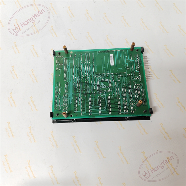
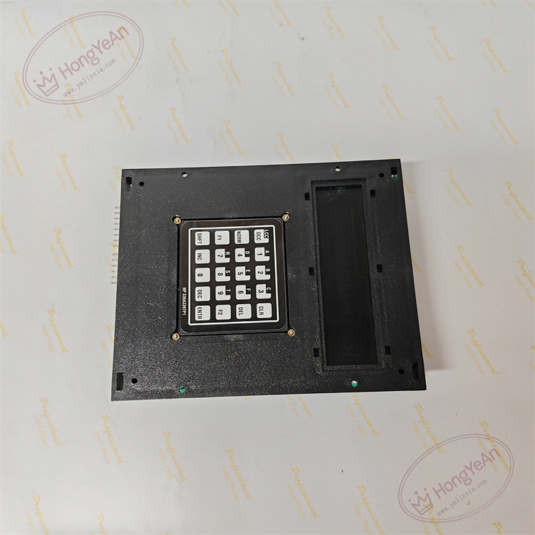
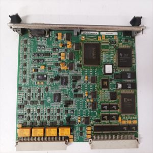
‑ Manufacturer: GE General Electric ‑ Compatible System: DC‑300, Speedtronic Mark‑V drive platform ‑ Functional Acronym: LCCBA (LAN Communication Board) ‑ Supported Protocol: ARCNET ‑ Connectors: ARCNET coaxial port, multi‑pin ribbon headers for backplane interface with DCCA controller ‑ On‑Board Jumpers: Station address and communication‑mode configuration jumpers. All jumper positions must be exactly duplicated during replacement ‑ Indicators: LED array for transmit, receive and communication‑fault diagnosis ‑ Power Source: +5 VDC, ±15 VDC supplied from drive‑rack backplane ‑ PCB Finish: Conformal coated multilayer PCB ‑ Compatibility Restriction: For DC‑300 / Mark‑V drive rack; incompatible with Mark‑VI / Mark‑VIe racks. G3 denotes hardware‑firmware revision.
Environmental Specifications
‑ Operating Temperature: 0 °C ~ +60 °C ‑ Storage Temperature: −40 °C ~ +85 °C ‑ Relative Humidity: 5%‑95 % non‑condensing ‑ Installation Environment: Drive‑control cabinet interior, Pollution Degree 2 ‑ EMC: Designed for power‑plant cabinet EMI and switching‑transient conditions
Mechanical Data
‑ Physical Dimension: approx 305 mm × 205 mm ‑ Mounting: Standard slot installation inside DC‑300 / Mark‑V drive rack ‑ Weight: approx 0.98 kg
Core Functions
- ARCNET bus communication: Real‑time data exchange between DCCA drive controller, local operator panel and plant supervisory system.
- Network gateway function: Uploads drive operating values, alarm information and trip event logs; downloads drive configuration parameters.
- Hardware station‑address setting: Jumpers set node address for multi‑drive network topology.
- Firmware‑based communication processing: EPROM stores dedicated ARCNET communication firmware.
- On‑board diagnostics: LED indicators assist commissioning and troubleshooting of network link faults.
Installation, Replacement & Critical Warnings
- Complete system power‑down and lock‑out procedure required before servicing. Non‑hot‑swappable. ESD wrist‑strap protection is mandatory for PCB and EPROM chips.
- Record original station‑address jumper positions before removal. Wrong address setting results in network conflict and total communication loss.
- Secure coaxial cable and ribbon‑cable connectors firmly; poor contact causes intermittent communication dropout.
- After power‑on, perform communication verification: check LED status, confirm data interaction between drive controller and HMI.
-
Common failure mode: Coaxial‑line surge damage to network transceiver circuits. Inspect ARCNET cabling when random communication errors occur.
Reviews
There are no reviews yet.